
Shaft Machining Services
- Fast prototype & low MOQ support
- Tight tolerance up to +0.002mm
- Surface finishing available
- Engineering review before production
Shaft Types We Machine
What we machine
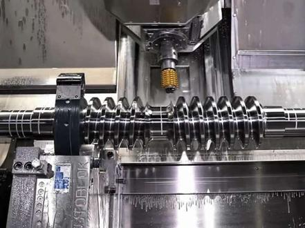
We provide custom shaft machining for prototypes, low-volume builds and production runs, using CNC turning, CNC milling, centerless grinding, cylindrical grinding, broaching, spline cutting, thread machining, heat treatment coordination and dimensional inspection. Whether the requirement is a hardened steel drive shaft, a stainless pump shaft, an aluminum actuator shaft or a complex stepped shaft with cross holes and flats, our process is built to help engineering and purchasing teams reduce risk from drawing review through shipment.Drive shafts
Typical Features
Stepped diameters, keyways, splines, threads, shouldersCommon Engineering Priorities
Torque capacity, concentricity, fatigue strength, runout controlTypical Features
Bearing journals, rotor seats, threaded ends, retaining groovesCommon Engineering Priorities
Balance, surface finish, bearing fit, shaft straightnessPump shafts
Typical Features
Seal diameters, impeller threads, coupling ends, corrosion-resistant materialsCommon Engineering Priorities
Seal performance, stainless material selection, wear and corrosion resistanceSpline shafts
Typical Features
Internal or external splines, lead-in chamfers, hardened surfacesCommon Engineering Priorities
Tooth profile accuracy, fit class, torque transfer, wear resistanceTypical Features
Integrated gear seats, journals, shoulders, threads and keywaysCommon Engineering Priorities
Coaxiality, gear alignment, load distribution, heat treatment distortionTypical Features
Ground outside diameters, hard chrome or hardened surfacesCommon Engineering Priorities
Straightness, smooth sliding, hardness, low frictionHollow shafts
Typical Features
Deep bores, internal threads, cross holes, thin-wall sectionsCommon Engineering Priorities
Wall thickness control, vibration, weight reduction, bore alignmentTypical Features
Splines or keyways, stepped diameters, bearing seats, gear mounting surfaces, threadsCommon Engineering Priorities
Torque transfer, torsional stiffness, fatigue resistance, alignment with gears, surface finishCustom stepped shafts
Typical Features
Multiple diameters, grooves, flats, holes and special end featuresCommon Engineering Priorities
Datum strategy, setup planning, cumulative tolerance controlWhen should a shaft be machined as one piece instead of assembled from multiple parts?
A one-piece shaft is often preferred when concentricity, torque transfer, leak prevention or compact design is critical. Multi-part assemblies may reduce machining complexity, but they can introduce tolerance stack-up, joint movement and additional inspection requirements. For high-speed rotation, sealed pump assemblies and precision drive applications, a single machined shaft can improve alignment and reduce assembly risk.
Materials for Custom Shaft Machining
Carbon and Alloy Steel Shafts
1045, 4140, 4340, 8620 and similar steels are commonly selected for drive shafts, gear shafts and general mechanical shafts. These materials provide a good balance of strength, fatigue resistance and machinability. Alloy steels can be heat treated for higher tensile strength or surface hardness.Stainless Steel Shafts
303, 304, 316, 17-4PH and 420 stainless steels are used where corrosion resistance, hygiene or washdown performance is required. Pump shafts, food equipment shafts and marine shafts often use stainless alloys. 17-4PH is frequently considered when both corrosion resistance and higher strength are required.Aluminum, Brass, Bronze and Specialty Materials
Aluminum shafts are used when weight reduction is important, while brass and bronze may be chosen for electrical, bearing or corrosion-related applications. Material selection should consider galling, shaft hardness, mating component hardness and lubrication.For demanding applications, our team can review material and heat treatment compatibility to avoid specifying a tolerance or surface finish that becomes impractical after hardening, nitriding, carburizing or plating.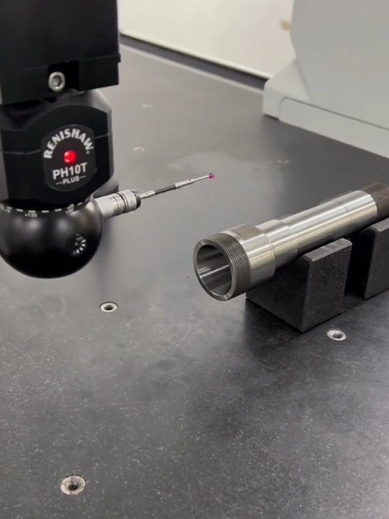
Precision Machining Processes for Shafts
1
CNC Turning
2
CNC Milling and Secondary Operations
3
Grinding and Finishing
Spline, Keyway and Thread Machining
Shafts often require torque-transmission features such as external splines, broached keyways, milled keyseats, rolled threads, cut threads or precision threaded ends. The manufacturing method is selected according to profile, quantity, tolerance class, hardness and mating component requirements.
Why is grinding often added after CNC turning?
CNC turning can be highly accurate, but grinding is often used when the shaft has bearing journals, seal seats or press-fit diameters with tight size, roundness or surface finish requirements. Grinding can also correct minor distortion after heat treatment and improve contact conditions with bearings, bushings or seals.
Real Engineering Problems We Help Prevent
Bearing Fit Variation Across Production Lots
Excessive Runout in a Stepped Motor Shaft
Seal Leakage on Pump Shafts
Why Precision Shaft Machining Requires More Than Basic Turning
Shafts often operate under torque, bending load, axial load, friction, vibration and thermal expansion. For that reason, a successful shaft machining project must control both geometry and material behavior. A turned diameter that meets size tolerance may still fail if the bearing journal has poor roundness, if a shoulder has a sharp stress riser, or if the heat treatment sequence causes distortion after finishing.
Our engineering review focuses on critical shaft features such as bearing seats, seal diameters, spline engagement zones, keyways, threads, snap-ring grooves, lubrication holes, shoulders, chamfers and transition radii. This helps identify manufacturing risks before cutting metal, especially when shafts require tight total indicator runout, close-fit assemblies or post-machining hardening.
- CNC turning for stepped shafts, journals, grooves, tapers and threaded features
- CNC milling for flats, slots, cross holes, keyways and special drive features
- Grinding for tight diameters, improved roundness and fine surface finish
- Heat treatment support for hardness, wear resistance and strength requirements
- Inspection reports for dimensional, geometric and surface finish verification
Engineering Controls That Improve Shaft Performance
Shaft failures are not always caused by incorrect material strength. Many problems begin with geometry, stress concentration, poor surface finish, inadequate fillets, misaligned features or excessive tolerance stack-up. Our manufacturability review helps customers identify issues that may not be obvious from a 2D drawing.
- Runout and concentricity: Important for rotating assemblies, bearings, couplings and seals.
- Straightness: Critical for long shafts, linear motion shafts and high-speed rotation.
- Surface finish: Affects seal life, bearing contact, sliding friction and fatigue performance.
- Fillet radius: Helps reduce stress concentration at shoulders and diameter transitions.
- Hardness depth: Important for wear surfaces, splines, gear seats and bearing journals.
- Datum structure: Controls how multiple diameters, holes and keyways relate to each other.
For example, on a long stainless pump shaft, moving a noncritical undercut away from a seal diameter and adding a controlled transition radius can reduce the risk of seal wear and fatigue cracking. On a motor shaft, defining the bearing journal as the primary datum can make inspection and assembly results more consistent.
When drawings include realistic GD&T, controlled datum references and function-based tolerances, shaft machining becomes more predictable. In many production cases, tolerance optimization can reduce unnecessary grinding, avoid special tooling and shorten inspection time while preserving the functional fit.
Typical Tolerances, Surface Finishes and Inspection Data
Final capability depends on shaft size, length, material, geometry and process route. The following values represent common engineering targets for precision shaft machining, not universal guarantees for every design.
| Feature or Requirement | Common Machining Target | Notes for Buyers and Engineers |
|---|---|---|
| Turned diameter tolerance | Approximately ±0.025 mm to ±0.05 mm | Depends on material, diameter and length-to-diameter ratio |
| Ground bearing journal tolerance | Approximately ±0.005 mm to ±0.013 mm | Often used for bearings, seals and precision fits |
| Surface finish after turning | Ra 1.6 μm to Ra 3.2 μm | Suitable for many general mechanical diameters |
| Surface finish after grinding | Ra 0.2 μm to Ra 0.8 μm | Used for sealing, sliding and bearing contact surfaces |
| Total indicator runout | Defined by functional datum and length | Long shafts may require special support and inspection setup |
| Hardness verification | HRC, HV or case depth check | Recommended after induction hardening, nitriding or carburizing |
Inspection may include micrometers, bore gauges, thread gauges, height gauges, surface roughness testers, hardness testers, CMM measurement, optical comparators and runout fixtures. For production orders, first article inspection and in-process control plans can help stabilize quality before full-volume machining.
Quality Documentation and Production Support
Precision shaft machining requires traceability and repeatability, especially for industrial equipment, automation systems, medical devices, aerospace support tooling and energy applications. Documentation can be adjusted to match the risk level and purchasing requirements of the project.
- Material certificates when required
- First article inspection reports
- Dimensional inspection reports for key shaft features
- Surface roughness measurement for sealing or bearing surfaces
- Hardness test results for heat-treated shafts
- Plating, coating or passivation certificates when applicable
- Process control plans for repeat production
Our goal is to provide machined shafts ready for assembly, not parts that require unexpected rework after delivery. For repeat orders, we can maintain process notes, tooling preferences and inspection history to improve consistency across batches.
What drawing information helps quote a shaft accurately?
The most useful information includes material grade, overall length, all diameter tolerances, surface finish requirements, heat treatment, hardness, coating, thread specifications, spline or keyway standards, datum references, GD&T requirements, annual quantity and whether inspection reports are required. A 3D CAD model plus a controlled 2D drawing is ideal.
Industries Served by Shaft Machining Services
Custom shafts are used in almost every mechanical system that transfers motion, supports rotation or guides linear movement. We support customers in industries where precision, repeatability and assembly fit are essential.
- Electric motors and generators
- Pumps, valves and fluid handling systems
- Gearboxes and power transmission equipment
- Robotics and automation machinery
- Medical and laboratory equipment
- Packaging and printing machinery
- Agricultural and construction equipment
- Marine and corrosion-resistant assemblies
- Energy, industrial maintenance and replacement parts
For procurement teams, reliable shaft machining means fewer supplier changes, fewer assembly disruptions and clearer documentation. For engineers, it means practical feedback on tolerances, datum choices, material selection and manufacturing sequence before production begins.
How to Specify a Shaft for Manufacturing
A well-defined shaft drawing shortens quoting time and reduces manufacturing ambiguity. The best specifications separate functional requirements from noncritical geometry, allowing the machining process to focus cost and inspection effort where performance truly depends on precision.
- Identify bearing journals, seal surfaces, press-fit areas and sliding diameters.
- Define datums based on how the shaft is assembled and inspected.
- Use GD&T for runout, concentricity, perpendicularity and position where needed.
- Specify surface finish only on functional surfaces instead of every diameter.
- Clarify heat treatment timing and final hardness requirements.
- Provide thread standards, spline standards, keyway dimensions and fit classes.
- Indicate acceptable burr limits, chamfers and edge-break requirements.
- Share expected production volume and inspection documentation needs.
If a drawing is still in development, we can review manufacturability and suggest practical changes. Small updates such as increasing tool clearance, adjusting an undercut, relaxing a nonfunctional tolerance or changing the process sequence can improve lead time and reduce unit cost without compromising performance.
Partner With a Precision Shaft Machining Supplier
Choosing the right shaft machining supplier is not only about price per part. It is about controlling risk in a component that often determines vibration, alignment, torque transfer, seal performance and service life. A capable supplier understands CNC turning, grinding, milling, heat treatment distortion, datum planning, inspection and the practical trade-offs between tolerance and cost.
We support custom shaft projects from early design review to production machining, with attention to material selection, feature sequencing, functional tolerances and documentation. If your project requires drive shafts, motor shafts, pump shafts, spline shafts, gear shafts, hollow shafts or other precision machined shafts, our team can help turn your requirements into reliable, manufacturable components.