Metal parts machining is the controlled removal of material from a workpiece to create components with defined geometry, surface finish and dimensional accuracy. For engineers, procurement teams and OEM buyers, choosing the right machining process affects cost, lead time, durability, assembly performance and long-term production stability.
This guide explains common processes, material choices, tolerances, quality controls and purchasing considerations for machining metal parts in prototype, low-volume and high-volume manufacturing environments.
What Is Metal Parts Machining?
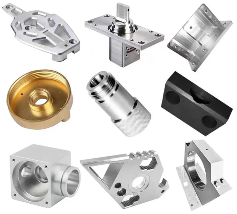
Metal parts machining is a subtractive manufacturing method used to produce components from bar stock, plate, castings, forgings or extrusions. Unlike additive manufacturing, machining starts with a solid blank and removes excess material through cutting, drilling, turning, milling, grinding or electrical discharge machining.
The process is widely used when parts require tight tolerances, accurate hole locations, controlled flatness, reliable threaded features or functional surfaces for sealing, sliding, fastening and alignment. Typical pièces métalliques usinées include shafts, housings, brackets, manifolds, flanges, heat sinks, precision spacers, valve bodies, gear blanks and automation fixtures.
In modern manufacturing, industrial metal machining usually refers to CNC-controlled production systems supported by CAD/CAM programming, toolpath simulation, in-process inspection and documented quality control.
Core Machining Processes for Metal Components
A single component may require multiple machining operations. Process selection depends on geometry, tolerance, material hardness, batch quantity, surface finish and cost target.
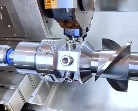
Fraisage CNC
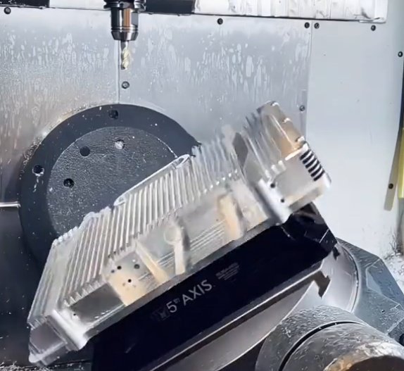
Fraisage CNC uses rotating cutting tools to remove material from a stationary or indexed workpiece. It is suitable for flat surfaces, pockets, slots, profiles, drilled holes, counterbores and complex 3D contours. Three-axis milling is efficient for simple prismatic parts, while four-axis and five-axis milling reduce setups for complex components.
Common applications include aluminum housings, stainless steel brackets, mold inserts, mounting plates and aerospace structural parts.
Tournage CNC
CNC turning rotates the workpiece while a cutting tool shapes external and internal diameters. It is ideal for cylindrical components such as shafts, bushings, pins, threaded fittings, nozzles and spacers. Live-tool turning centers can also mill flats, slots and cross holes in the same setup.
Drilling, Boring and Tapping
Drilling creates holes, boring improves hole accuracy and tapping forms internal threads. These operations are critical because hole position, thread depth and perpendicularity often determine whether a part assembles correctly. For high-reliability components, thread gauges, plug gauges and coordinate measuring machines are commonly used for verification.
Grinding and Honing
Grinding and honing are finishing processes used when parts require very fine surface finish, roundness, flatness or dimensional repeatability. They are common for bearing seats, hydraulic components, hardened steel parts and sealing surfaces.
EDM Machining
Electrical discharge machining, or EDM, removes metal using electrical sparks rather than conventional cutting force. Wire EDM is useful for hard materials, sharp internal profiles and thin-wall features. Sinker EDM is often used for cavities, dies and mold components.
Materials Used in Metal Parts Machining
Material choice influences machinability, tool life, heat treatment, corrosion resistance, weight, strength and cost. A technically correct drawing should specify material grade, heat treatment condition and any applicable standard.
| Groupe de matériaux | Notes communes | Machining Notes | Applications typiques |
|---|---|---|---|
| Aluminium | 6061-T6, 7075-T6, 2024 | High machinability, fast cycle times, good strength-to-weight ratio | Housings, brackets, heat sinks, aerospace and automation parts |
| Acier inoxydable | 304, 316, 17-4PH, 303 | Corrosion resistant; requires correct tooling and coolant control | Medical devices, food equipment, marine fittings, valve components |
| Carbon and Alloy Steel | 1018, 1045, 4140, 4340 | Good strength and wear resistance; may require heat treatment | Shafts, gears, fixtures, machine components, structural parts |
| Brass and Copper | C360, C110, C101 | Brass machines easily; copper requires sharp tools and heat control | Electrical contacts, fittings, terminals, thermal components |
| Titane | Grade 2, Grade 5 Ti-6Al-4V | High strength and low thermal conductivity; slower feeds and speeds | Aerospace, medical implants, high-performance mechanical parts |
| Acier à outils | D2, A2, H13, O1 | Often machined before heat treatment, then ground to final tolerance | Dies, punches, mold tooling, wear plates |
Engineering note: machinability is not the same as material strength
A strong material is not always difficult to machine, and a softer material is not always easy to machine. For example, 303 stainless steel usually machines more efficiently than 304 stainless steel because sulfur improves chip breaking. Pure copper is soft but can be challenging because it tends to smear and conduct heat rapidly.
Tolerances, Surface Finish and Feature Control
Tolerances define the acceptable variation from nominal dimensions. Overly tight tolerances increase inspection time, tool wear, scrap risk and machining cost. A practical drawing separates critical-to-function dimensions from non-critical features.
As a general reference, many CNC machined metal parts can hold tolerances around ±0.005 in or ±0.13 mm under standard conditions. Precision features may be held to ±0.001 in or ±0.025 mm, but this depends on part size, material stability, feature geometry, machine capability and inspection method.
| Exigence | Typical Practical Range | Cost Impact | Engineering Comment |
|---|---|---|---|
| General machined dimensions | ±0.005 in / ±0.13 mm | Modéré | Suitable for many brackets, housings and non-mating features |
| Precision bores and bearing fits | ±0.0005 to ±0.0015 in / ±0.013 to ±0.038 mm | Haut | May require boring, reaming, grinding or honing |
| Finition de la surface | Ra 3.2 to 0.8 µm common | Moderate to high | Critical for sealing, sliding and cosmetic surfaces |
| Flatness or parallelism | Application-dependent | High for large thin parts | Material stress relief and fixture strategy may be required |
Drawings often reference ISO 2768 for general tolerances or ASME Y14.5 for geometric dimensioning and tolerancing. When GD&T is used correctly, it communicates function more clearly than plus/minus tolerances alone.
Design for Manufacturability in Machined Metal Parts
Design for manufacturability, often called DFM, reduces unnecessary machining time while preserving product performance. The best cost reductions usually come before production begins, when the engineering team can still adjust geometry, tolerances and material specifications.
- Use standard stock sizes where possible to reduce material waste and roughing time.
- Avoid deep narrow pockets unless they are functionally required.
- Specify larger internal radii so standard end mills can be used.
- Limit tight tolerances to mating, sealing, bearing or alignment features.
- Provide clear thread specifications, including thread class and minimum depth.
- Consider part orientation and fixturing access during design reviews.
- Use symmetrical geometry carefully, because it can create assembly ambiguity if orientation matters.
A common real-world issue is thin-wall distortion. For example, an aluminum housing with 1.5 mm walls may measure within tolerance immediately after machining but shift after unclamping because residual stresses are released. Solutions may include rough machining, stress relief, finish machining, improved fixturing or revised wall thickness.
Example: how a small design change can reduce machining cost
A stainless steel valve block originally required three setups because ports were placed on five faces. By moving two auxiliary ports to an accessible face and increasing internal corner radii from 1.0 mm to 2.5 mm, the part could be machined in two setups with standard tooling. In a 500-piece run, estimated cycle time dropped from 42 minutes to 31 minutes per part, reducing machining time by approximately 26%.
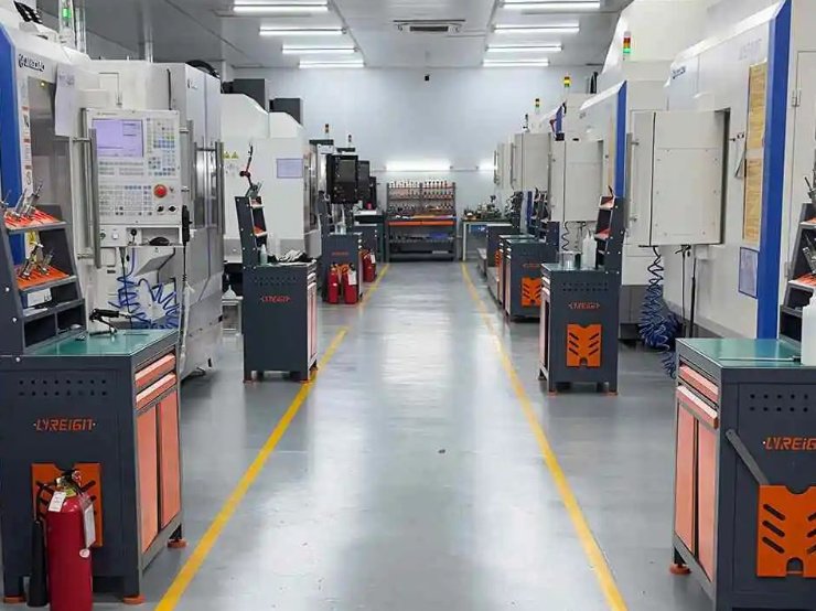
Industrial Metal Machining for Production: Planning, Capacity and Repeatability
Production usinage des métaux is not only about making one correct part. It is about making every part consistently within specification while controlling cost, delivery and quality risk. In an industrial environment, process stability is built through machine selection, tooling strategy, fixture design, inspection planning and production documentation.
Prototype Versus Production Requirements
Prototype machining often prioritizes speed, design validation and engineering flexibility. Production machining emphasizes repeatability, takt time, process capability and supply continuity. A supplier that performs well on prototypes may still need additional planning for production parts, especially when annual volume, inspection records or traceability requirements increase.
Fixture Strategy
Fixtures locate and hold the part during machining. Poor fixturing can cause vibration, distortion, inconsistent datum alignment and dimensional variation. For repeat production, dedicated fixtures may increase upfront cost but reduce cycle time and improve repeatability.
Tooling and Cycle Time
Tool selection affects surface finish, dimensional control and productivity. Carbide tooling, high-pressure coolant, chip evacuation and tool wear monitoring are especially important for stainless steel, titanium and high-volume aluminum machining.
For buyers, cycle time is not the only cost driver. Setup time, inspection frequency, material yield, secondary operations, packaging requirements and supplier quality performance also influence total landed cost.
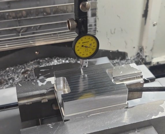
Quality Control and Inspection Methods
Reliable metal parts machining depends on measurable quality controls. Inspection should be matched to the risk level of the part. A simple spacer may need calipers and thread gauges, while an aerospace bracket may require CMM inspection, material certification and full dimensional reporting.
- CMM inspection verifies complex geometry, GD&T callouts, hole positions and datum structures.
- Micrometers and bore gauges measure high-precision diameters and thicknesses.
- Surface roughness testers measure Ra values for sealing or sliding surfaces.
- Go/no-go gauges support fast production checks for threads and fit features.
- Material certificates confirm alloy grade, heat treatment and compliance requirements.
- First article inspection reports document dimensional compliance before production release.
Many industrial buyers request inspection plans based on ISO 9001 quality systems. Automotive, aerospace, medical and defense-related applications may require additional documentation, traceability and process controls.
Common inspection problem: datum mismatch between drawing and fixture
A machined bracket can fail CMM inspection even when the machine process is stable if the supplier fixtures the part from a surface that does not match the drawing datum scheme. During quoting and DFM review, engineers should confirm which surfaces are used for machining, inspection and assembly alignment.
Secondary Operations and Finishing Options
Machined metal parts often require secondary operations after cutting. These processes improve appearance, corrosion resistance, hardness, cleanliness or assembly performance.
| Finishing Process | Compatible Materials | Primary Benefit | Design Consideration |
|---|---|---|---|
| Anodisation | Aluminium | Corrosion resistance, wear resistance, color options | Can affect dimensions; masking may be needed |
| Passivation | Acier inoxydable | Improves corrosion resistance by removing free iron | Part must be cleaned properly before treatment |
| Black oxide | Steel, stainless steel | Low-reflective appearance and mild corrosion protection | Often requires oil or sealant for better protection |
| Heat treatment | Steel, stainless steel, aluminum, titanium | Improves strength, hardness or wear resistance | May cause distortion; finish machining may be required |
| Electroless nickel plating | Steel, aluminum, copper alloys | Uniform coating, corrosion and wear resistance | Thickness must be considered in final tolerances |
| Deburring and edge breaking | Most metals | Removes sharp edges and loose burrs | Critical for safety, assembly and cleanliness |
Cost Drivers in Metal Parts Machining
Machined part cost is determined by more than material weight. Engineers and buyers can make better sourcing decisions by understanding the factors that influence quoting.
- Material grade and availability: titanium, 17-4PH stainless steel and certified aerospace alloys cost more than standard aluminum or low-carbon steel.
- Part complexity: more faces, deep pockets, undercuts and tight inside corners increase machining time.
- Number of setups: each reorientation adds labor, inspection risk and fixture complexity.
- Tolerance requirements: precision fits require slower machining and more inspection.
- Surface finish: fine finishes may require additional tool passes or grinding.
- Order quantity: higher volume spreads setup cost across more parts and may justify dedicated tooling.
- Documentation: full traceability, first article inspection and compliance reports add administrative and inspection time.
A useful sourcing practice is to request both prototype and production pricing. A one-piece prototype price may be dominated by programming and setup, while a 1,000-piece production price is more sensitive to cycle time, tool wear and inspection frequency.
Supplier Evaluation Checklist for Engineers and Buyers
Selecting a machining supplier should involve technical capability, communication quality and risk management. The lowest unit price is not always the lowest total cost if parts arrive late, require rework or fail assembly.
- Can the supplier machine the specified material grade and thickness or diameter?
- Do they have CNC milling, CNC turning, EDM, grinding or secondary processes required for the part?
- Can they hold the required tolerances on the actual part size and geometry?
- Do they understand GD&T, datum structures and inspection requirements?
- Can they provide material certificates, inspection reports and finishing documentation?
- Do they offer DFM feedback before production release?
- Can they support scaling from prototype to repeat production?
- Do they have a clear process for nonconforming parts and corrective actions?
For complex or high-value components, buyers should share 3D CAD files, 2D drawings, annual usage estimates, target lead time, inspection requirements and finishing specifications. Complete technical information reduces quoting uncertainty and improves supplier accountability.
Conclusion: Matching Machining Capability to Part Function
Metal parts machining remains one of the most reliable manufacturing methods for precision components because it combines material strength, dimensional accuracy and process flexibility. The best results come from aligning design intent, material selection, tolerance strategy, inspection planning and supplier capability.
Whether the requirement is a single prototype, a low-volume custom component or a repeat production program, successful machining depends on clear engineering requirements and practical manufacturing decisions. By considering tolerances, geometry, material behavior, finishing needs and quality documentation early, teams can reduce cost, shorten lead time and improve part performance.