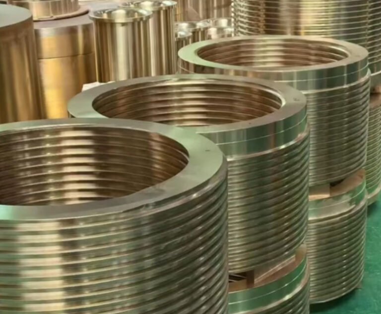
A gear shaft is a rotating mechanical component that integrates a shaft body with gear teeth, splines, keyways, bearing journals or coupling features to transmit torque between machine elements. It is widely used in gearboxes, automotive drivetrains, industrial reducers, electric motors, agricultural machinery, construction equipment, marine propulsion systems and automation equipment.
For engineers and buyers, the main search intent behind “gear shaft” is usually practical: how to specify the right part, which material and heat treatment to choose, what tolerances matter, and how to evaluate a machining supplier. This page explains the design, manufacturing and procurement factors that directly affect performance, cost and delivery reliability.
What Is a Gear Shaft?
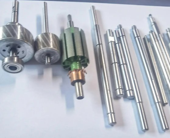
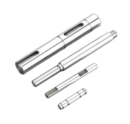
A gear shaft combines torque transmission and rotational support in one part. Unlike a simple gear mounted on a separate shaft, an integrated gear shaft can improve concentricity, reduce assembly error and increase stiffness. Typical features include gear teeth, splines, shoulders, bearing seats, oil grooves, circlip grooves, threads and center holes.
The functional surfaces of a gear shaft are normally divided into three zones: the gear tooth area for power transmission, the bearing journal area for rotational support, and the connection area for torque input or output. Tooth accuracy, shaft runout and heat-treated hardness are the three variables that most often determine service life.
Common Types of Gear Shafts
Gear shafts can be classified by tooth geometry, shaft configuration, assembly method and operating environment. Selecting the correct type helps reduce vibration, avoid premature tooth wear and improve gearbox efficiency.
| Type | Typical Features | Common Applications |
|---|---|---|
| Spur gear shaft | Straight teeth, simple structure, high machining efficiency | Industrial reducers, conveyors, packaging machines |
| Helical gear shaft | Angled teeth, smoother meshing, higher axial force | Automotive transmissions, high-speed gearboxes, compressors |
| Pinion shaft | Small gear integrated with a shaft, often used as a drive member | Rack and pinion systems, steering systems, reduction drives |
| Splined gear shaft | External or internal splines for sliding or fixed torque transfer | PTO shafts, hydraulic motors, vehicle drivetrains |
| Worm gear shaft | Screw-like tooth profile, high reduction ratio | Lifting mechanisms, actuators, indexing equipment |
| Bevel gear shaft | Conical gear geometry for intersecting shafts | Differentials, angle drives, marine gear systems |
When should an integrated gear shaft be used instead of a separate gear and shaft?
An integrated gear shaft is preferred when concentricity, compactness and torsional stiffness are critical. It also reduces assembly stack-up errors. A separate gear and shaft may be more economical when the gear is large, replacement is frequent, or different gear ratios must be assembled on the same shaft platform.
Gear Shaft Materials
Material selection depends on torque, impact load, tooth contact stress, shaft bending stress, heat treatment process and operating environment. The most common choices are alloy steels because they provide a strong balance of core toughness and surface hardness.
| Material | Equivalent or Common Standard | Typical Use | Engineering Benefit |
|---|---|---|---|
| 20CrMnTi | Chinese alloy carburizing steel | Automotive and reducer gear shafts | Good carburizing response and wear resistance |
| 8620 | SAE/AISI 8620 | Pinion shafts and transmission components | Tough core with hard carburized case |
| 4140 | SAE/AISI 4140, 42CrMo4 | Heavy-duty shafts and medium-load gears | High strength after quenching and tempering |
| 4340 | SAE/AISI 4340 | High-load aerospace and defense shafting | Excellent fatigue strength and toughness |
| 1045 | C45, S45C | Low to medium duty gear shafts | Cost-effective, easy to machine |
| 17-4PH stainless steel | UNS S17400 | Corrosion-resistant mechanical drives | Good strength with improved corrosion resistance |
For high-load transmission applications, carburizing steels such as 8620 and 20CrMnTi are often selected because they allow a hard wear-resistant surface while maintaining a ductile core. For large industrial shafts where through strength is more important than case hardness, quenched and tempered 4140 or 42CrMo4 can be more suitable.
Heat Treatment and Surface Hardness
Heat treatment has a direct influence on wear resistance, bending fatigue and tooth pitting life. The process should be selected according to the tooth load, shaft diameter, case depth and distortion control requirements.
- Carburizing and quenching: Common for high-performance gear shafts. Typical surface hardness is 58–62 HRC with an effective case depth of 0.6–1.5 mm, depending on module and load.
- Induction hardening: Suitable for localized hardening of teeth, splines or bearing journals. It reduces processing time and limits heat-affected zones.
- Nitriding: Provides high surface hardness, good wear resistance and lower distortion than carburizing. Common hardness can exceed 900 HV depending on material.
- Quenching and tempering: Used for shafts requiring high core strength and impact resistance. Typical hardness ranges from 28–38 HRC for many 4140-type shafts.
- Stress relieving: Applied after rough machining or welding-related operations to improve dimensional stability before finishing.
Heat-treatment distortion must be considered before final grinding. For precision gear shafts, manufacturers typically leave grinding allowance on bearing journals and critical diameters after carburizing or induction hardening.
Key Design Parameters for Gear Shafts
A reliable gear shaft design must satisfy tooth strength, shaft bending strength, torsional stiffness, bearing fit and manufacturing feasibility. The following parameters should be defined before production drawings are released.
Gear Tooth Data
- Module or diametral pitch
- Number of teeth
- Pressure angle, commonly 20 degrees for many industrial gears
- Helix angle for helical gear shafts
- Face width
- Profile shift coefficient if applicable
- Tooth accuracy grade according to ISO, DIN or AGMA standards
Shaft Geometry
- Overall length and stepped diameter layout
- Bearing journal diameter and tolerance class
- Shoulder radii and relief grooves
- Internal or external threads
- Keyway width, depth and end radius
- Spline specification, such as involute spline or straight-sided spline
- Center holes for turning and cylindrical grinding
Load and Operating Conditions
- Input torque and peak torque
- Rotational speed in rpm
- Duty cycle and shock load factor
- Lubrication method and oil viscosity
- Operating temperature
- Contamination risk, including dust, moisture or abrasive particles
What information should be included in a gear shaft drawing?
A complete drawing should include material grade, heat treatment, hardness range, gear tooth data, shaft tolerances, geometric tolerances, surface roughness, inspection standards, coating requirements, batch traceability and any special packaging instructions. For gears, tooth accuracy grade and measurement over pins or span measurement should also be specified.
Gear Shaft Machining Process
Gear shaft manufacturing usually combines turning, milling, gear cutting, heat treatment, grinding and inspection. A robust process plan reduces distortion, improves repeatability and prevents expensive rework.
- Material preparation: Bar stock, forging or near-net-shape blank is selected according to strength and volume requirements.
- Rough turning: CNC turning forms stepped diameters, shoulders, center holes and initial reference surfaces.
- Rough milling or drilling: Oil holes, flats, keyways or threaded holes may be added before heat treatment.
- Gear cutting: Gear hobbing, shaping, milling, skiving or grinding creates the tooth profile.
- Spline machining: Splines can be hobbed, broached, rolled, shaped or ground depending on accuracy and volume.
- Heat treatment: Carburizing, induction hardening, nitriding or quenching and tempering is performed based on drawing requirements.
- Straightening: Shafts are checked and corrected if heat treatment causes bending.
- Finish grinding: Bearing journals, seal surfaces and critical diameters are ground to final tolerance.
- Gear finishing: Shaving, honing, lapping or grinding improves tooth accuracy and surface finish.
- Final inspection: Dimensional, hardness, runout, tooth profile and surface quality checks are completed before packaging.
For precision gear shafts, the datum strategy is as important as the cutting method. If turning, hobbing and grinding use inconsistent reference surfaces, the final part may meet individual diameter tolerances but fail total runout or gear-to-journal concentricity requirements.
Tolerances, Runout and Surface Finish
Gear shaft tolerances depend on the gearbox accuracy class, speed, noise requirements and bearing type. High-speed drives require tighter runout and smoother tooth finish to control vibration and noise.
| Feature | Typical Precision Range | Why It Matters |
|---|---|---|
| Bearing journal diameter | IT5–IT7 depending on bearing fit | Controls bearing preload, clearance and service temperature |
| Journal roundness | 0.003–0.010 mm for precision shafts | Reduces bearing vibration and uneven load distribution |
| Gear pitch accuracy | ISO 5–8 for many industrial applications | Affects transmission error, noise and load sharing |
| Total runout of gear to journals | 0.01–0.05 mm depending on size and speed | Prevents cyclic tooth load and premature pitting |
| Ground journal surface roughness | Ra 0.2–0.8 μm | Improves bearing contact and seal performance |
| Tooth flank roughness | Ra 0.4–1.6 μm depending on finishing method | Influences friction, lubrication film and wear |
In one common industrial reducer case, reducing gear-to-bearing-journal runout from 0.06 mm to below 0.02 mm can significantly reduce mesh vibration and improve bearing temperature stability. The exact result depends on speed, load, housing stiffness and lubrication, but this tolerance improvement is often more effective than simply increasing material hardness.
Inspection and Quality Control
Gear shaft quality control should verify both dimensional accuracy and functional performance. For critical applications, inspection records should be traceable to material heat number, heat treatment batch and machining lot.
- CMM inspection: Measures geometry, position, coaxiality and complex datum relationships.
- Gear measuring center: Checks profile deviation, lead deviation, pitch error and total cumulative pitch deviation.
- Runout testing: Confirms concentricity between gear teeth, journals and spline features.
- Hardness testing: Verifies surface hardness and core hardness after heat treatment.
- Case depth measurement: Confirms effective carburized or hardened layer depth.
- Magnetic particle inspection: Detects surface cracks after forging, machining or heat treatment.
- Surface roughness testing: Ensures journals, seal areas and tooth flanks meet functional requirements.
Inspection should be matched to risk. A prototype shaft may need full dimensional reports and material certificates, while a mature production shaft may use statistical process control with periodic full layout inspection.
Which standards are commonly referenced for gear shaft inspection?
Common references include ISO 1328 for cylindrical gear accuracy, DIN 3962 for gear tolerances, AGMA standards for gear rating and accuracy, ISO 286 for fits and tolerances, ISO 1101 for geometric tolerancing, and ASTM or ISO standards for material and hardness testing. The applicable standard should be clearly stated on the drawing or purchase specification.
Common Engineering Problems and Practical Solutions
Gear shaft failures often come from a combination of design, heat treatment, machining and assembly issues. Understanding failure modes helps engineers prevent repeat problems.
| Problem | Likely Cause | Practical Solution |
|---|---|---|
| Tooth pitting | High contact stress, poor lubrication, low surface hardness | Increase case hardness, improve lubrication, optimize tooth contact pattern |
| Shaft bending fatigue | Sharp shoulder radius, overload, insufficient core strength | Increase fillet radius, use stronger alloy steel, improve heat treatment |
| Excessive gearbox noise | Pitch error, lead error, runout, poor tooth surface finish | Improve gear finishing, control datum alignment, specify tighter gear accuracy |
| Bearing overheating | Incorrect fit, poor roundness, misalignment, lubrication failure | Review bearing fit, grind journals, check housing alignment and oil flow |
| Spline wear | Fretting, insufficient hardness, misalignment, lack of lubrication | Apply induction hardening or nitriding, improve fit, use suitable lubricant |
| Heat treatment cracks | Material defects, sharp corners, excessive quench severity | Improve material inspection, add relief radii, adjust quenching process |
How Buyers Should Specify a Custom Gear Shaft
Purchasing a gear shaft is not only a price comparison. A low-cost shaft can become expensive if it causes assembly delays, gearbox noise or warranty claims. Buyers should evaluate supplier capability, process control and inspection support before placing production orders.
Recommended RFQ Information
- 2D drawing with tolerances and geometric dimensioning
- 3D model in STEP, IGES or native CAD format
- Material grade and acceptable equivalents
- Heat treatment process, hardness and case depth
- Annual volume and batch quantity
- Required gear accuracy standard
- Surface treatment, coating or rust prevention requirements
- Inspection report format and certificate requirements
- Packaging requirements for ground surfaces and gear teeth
Supplier Evaluation Checklist
- Experience with gear hobbing, shaping, skiving, grinding or spline machining
- Ability to control heat-treatment distortion and perform post-heat-treatment grinding
- Access to gear measuring equipment, CMM and hardness testing
- Understanding of ISO, DIN or AGMA gear standards
- Documented process flow, control plan and traceability system
- Capacity for prototypes, small batches and stable volume production
A strong gear shaft supplier should discuss manufacturability before quoting. If a drawing contains unrealistic tolerances, missing datum references or incompatible material and heat treatment requirements, early engineering feedback can prevent cost overruns and delivery delays.
Applications of Gear Shafts
Gear shafts are found wherever compact torque transmission and accurate rotation are required. The required design varies widely by industry.
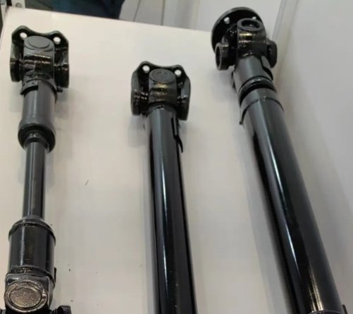
- Automotive: Transmission shafts, differential pinion shafts, steering pinions and electric vehicle reducer shafts.
- Industrial gearboxes: Input shafts, intermediate shafts and output shafts for conveyors, mixers, pumps and crushers.
- Agricultural machinery: PTO gear shafts, harvester transmission shafts and implement drive components.
- Construction equipment: Heavy-duty reduction gear shafts for excavators, loaders and cranes.
- Robotics and automation: Compact precision gear shafts for servo reducers, actuators and indexing systems.
- Marine equipment: Corrosion-resistant or high-strength shafts for propulsion and auxiliary systems.
- Energy equipment: Gear shafts for wind turbine gearboxes, oilfield machinery and power generation systems.
Cost Drivers in Gear Shaft Manufacturing
The cost of a gear shaft is influenced by size, material, tooth accuracy, heat treatment, grinding requirements and inspection level. Understanding these drivers helps buyers optimize cost without compromising performance.
| Cost Driver | Impact on Price | Optimization Option |
|---|---|---|
| Material grade | Alloy steels and stainless steels cost more than carbon steel | Use equivalent materials only after engineering approval |
| Tooth accuracy | Higher accuracy may require grinding or honing | Specify the accuracy actually needed by speed and noise targets |
| Heat treatment | Carburizing and nitriding add process time and inspection needs | Match case depth and hardness to real load conditions |
| Grinding tolerance | Tight journal tolerances increase setup and cycle time | Apply tight tolerances only to functional surfaces |
| Batch quantity | Low volume increases unit setup cost | Combine similar parts or use family tooling when possible |
| Inspection requirements | Full reports and advanced testing increase quality cost | Use risk-based inspection plans for mature production |
A well-specified gear shaft balances strength, accuracy, manufacturability and inspection. For demanding applications, the best value usually comes from early collaboration between design engineers, manufacturing engineers and procurement teams.