A bearing shaft is the rotating or stationary cylindrical component that supports a bearing inner ring, bearing sleeve, bushing, gear, pulley, coupling or wheel hub. In rotating machinery, the shaft must transmit torque, maintain alignment, resist bending and provide a precise bearing journal so that the bearing can operate with controlled load distribution, low vibration and predictable service life.
This page explains how bearing shafts are specified, manufactured and inspected, including shaft materials, bearing fits, journal tolerances, surface roughness, heat treatment, machining sequence, failure modes and buyer-side technical requirements.
- Primary search intent covered: what a bearing shaft is and how to specify one.
- Engineering intent covered: tolerance, runout, roughness, hardness and fit selection.
- Procurement intent covered: drawing data, inspection records and supplier evaluation points.
- Manufacturing intent covered: turning, grinding, heat treatment, straightening and quality control.
What Is a Bearing Shaft?
A bearing shaft is a machined shaft with one or more bearing seats, also called bearing journals. The journal is the area where the bearing inner ring or sleeve bearing runs. Depending on the equipment design, the shaft may rotate inside stationary bearings, or the shaft may remain fixed while the bearing outer component rotates around it.
The performance of a bearing shaft depends on more than diameter. Important features include shaft straightness, concentricity, shoulder squareness, transition radius, keyway accuracy, surface finish, residual stress, hardness profile and dynamic balance.
| Term | Meaning | Why It Matters |
|---|---|---|
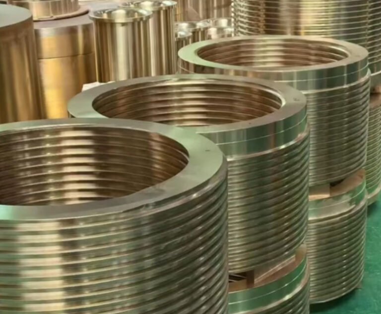
| Bearing journal | Precision cylindrical seat for a bearing or bushing | Controls fit, alignment and bearing load distribution |
| Shaft shoulder | Axial locating face next to the bearing seat | Prevents bearing creep and controls axial positioning |
| Fillet radius | Transition radius between shaft diameter changes | Reduces stress concentration and must clear bearing chamfer |
| Runout | Variation of rotating surface relative to the datum axis | Affects vibration, seal life and bearing temperature |
| Interference fit | Bearing bore is slightly smaller than shaft seat | Prevents inner ring rotation on the shaft under load |
Main Types of Bearing Shafts
Bearing shafts are not one-size-fits-all. The correct type depends on load, speed, bearing arrangement, lubrication method, assembly process and maintenance access.
Rotating Bearing Shaft
In motors, pumps, gearboxes, fans, rollers and spindles, the shaft rotates while bearings support radial and axial loads. This type usually requires controlled concentricity between multiple bearing seats and driven features such as gears, pulleys or couplings.
Stationary Bearing Shaft
A stationary shaft, sometimes called a fixed axle or support pin, carries a rotating wheel, roller or pulley through bearings. It is common in conveyor rollers, idler wheels, agricultural equipment and material handling systems.
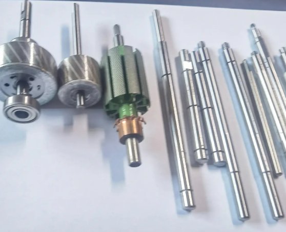
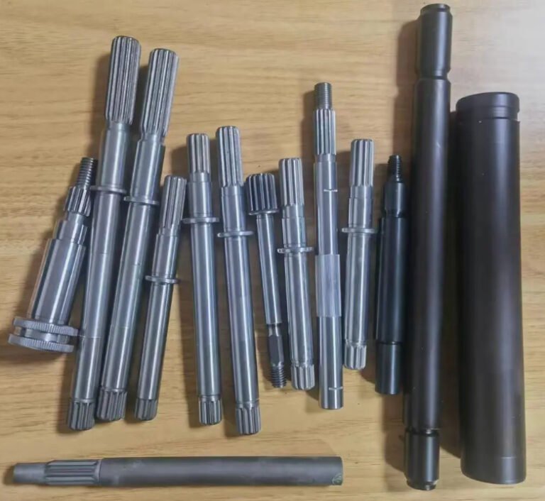
Stepped Bearing Shaft
A stepped shaft has several diameters for bearings, seals, gears, spacers, retaining rings and shoulders. It allows accurate axial location but requires careful control of shoulder perpendicularity and stress concentration.
Hardened Bearing Shaft
Hardened shafts are used where wear resistance, rolling contact strength or repeated assembly is required. Common options include induction hardening, through hardening, carburizing, nitriding and hard chrome plating, depending on the load and environment.
Precision Ground Bearing Shaft
Precision ground shafts are used in machine tools, linear motion systems, high-speed motors, printing machinery, medical equipment and test rigs. Grinding improves diameter accuracy, cylindricity and surface roughness after turning or heat treatment.
Key Design Requirements for a Bearing Shaft
A bearing shaft must satisfy three engineering objectives: transmit load, maintain bearing geometry and survive operating conditions. Design should start from load case, speed, bearing type and duty cycle rather than shaft diameter alone.
- Radial load: force perpendicular to the shaft axis, common in belt drives, wheels and rollers.
- Axial load: thrust force along the shaft axis, common in pumps, screw drives and helical gear systems.
- Bending moment: deflection caused by unsupported spans or overhung loads.
- Torsional load: torque transmitted through couplings, gears, splines or keyways.
- Speed: affects bearing heat generation, balance grade, lubricant selection and critical speed.
- Environment: moisture, dust, chemicals, temperature and washdown conditions influence material and coating.
For rotating equipment, radial runout and shaft deflection are often more important than static strength. A shaft that is strong enough may still cause premature bearing failure if the journal axis is misaligned or if the shoulder face is not square to the bearing seat.
Bearing Shaft Materials and Heat Treatment
Material selection should match load, wear, corrosion risk, machinability and required hardness. The following table summarizes common choices used for bearing shafts.
| Material | Common Use | Typical Advantage | Notes |
|---|---|---|---|
| C45 / AISI 1045 medium carbon steel | General machinery shafts, rollers, moderate-load drives | Good machinability and strength | Can be induction hardened on bearing journals |
| 42CrMo4 / AISI 4140 alloy steel | High-load shafts, gear shafts, hydraulic equipment | High toughness and fatigue strength | Often quenched and tempered |
| 20CrMnTi / carburizing steel | Gear shafts and high-wear bearing seats | Hard surface with tough core | Requires carburizing and grinding allowance |
| AISI 304 stainless steel | Food equipment, light-duty corrosion environments | Corrosion resistance | Lower hardness and strength than alloy steels |
| AISI 440C stainless steel | Precision shafts, corrosion-resistant wear applications | Can be hardened to high hardness | More brittle than many alloy steels |
| GCr15 / AISI 52100 bearing steel | High-hardness precision shafts, linear bearing shafts | Excellent wear and rolling contact fatigue resistance | Requires careful heat treatment and grinding |
In many industrial shafts, surface finish and hardness are specified together. For example, a hardened bearing journal may require 55 to 62 HRC with Ra 0.2 to 0.8 μm after grinding, while a general bearing seat for a standard rolling bearing may use Ra 0.8 to 1.6 μm depending on fit and speed.
Engineering note: heat treatment and shaft distortion
Heat treatment improves strength and wear resistance, but it can also cause bending, diameter growth, ovality and residual stress. For precision bearing shafts, the usual process is rough turning, stress relieving or quenching and tempering, semi-finish turning, straightening if required, finish grinding and final inspection. Grinding allowance must be planned before heat treatment.
Bearing Shaft Tolerances, Fits and Surface Finish
Bearing shaft tolerance should be selected according to bearing type, load direction, ring rotation condition and assembly method. A loose fit may allow fretting or creep, while excessive interference can reduce internal bearing clearance and increase operating temperature.
The shaft tolerance zone is commonly specified according to ISO 286 fit designations such as h6, j6, k6, m6, n6 or p6. For metric rolling bearings, the correct fit depends on whether the bearing inner ring rotates relative to the load.
| Operating Condition | Typical Shaft Fit Direction | Engineering Reason |
|---|---|---|
| Light load, stationary inner ring load | Clearance or transition fit may be acceptable | Easier assembly and disassembly |
| Rotating inner ring under radial load | Transition to interference fit | Prevents ring creep on the shaft |
| Heavy shock load or vibration | Stronger interference fit | Improves seating stability |
| High-speed precision spindle | Controlled precision fit | Manages heat, preload and runout |
Typical engineering targets for precision bearing seats may include:
- Diameter tolerance: commonly IT5 to IT7 depending on shaft size and application.
- Cylindricity: often tighter than the diameter tolerance for high-speed shafts.
- Total indicated runout: commonly 0.005 to 0.03 mm for precision rotating equipment.
- Shoulder face runout: controlled to maintain correct bearing seating.
- Surface roughness: Ra 0.2 to 1.6 μm depending on bearing, speed and fit.
The combination of shoulder height, fillet radius, and chamfer must match the bearing manufacturer’s dimensions. A fillet that is too large may prevent the bearing from seating fully against the shoulder; a fillet that is too sharp increases fatigue risk.
Machining Process for Bearing Shafts
Bearing shaft manufacturing usually involves a controlled sequence rather than a single turning operation. The exact route depends on shaft length, diameter, tolerance, hardness and surface finish.
- Material inspection: confirm grade, diameter, heat number and certificate requirements.
- Cutting and blank preparation: saw cut or forged blank prepared with machining allowance.
- Center drilling: establish centers for turning and grinding between centers.
- Rough turning: remove excess stock and form basic steps.
- Stress relief or heat treatment: reduce internal stress or achieve strength and hardness.
- Semi-finish turning: machine journals, shoulders, grooves, threads, keyways or splines close to final size.
- Grinding or hard turning: finish bearing seats to required tolerance and roughness.
- Deburring and edge control: remove burrs from keyways, grooves and chamfers.
- Inspection: verify dimensions, runout, roughness, hardness and geometric tolerances.
- Protection and packing: apply anti-rust oil, caps or sleeves to protect bearing journals.
For long slender shafts, machining centers and cylindrical grinders must control support pressure from centers, steady rests and follow rests. Excessive clamping force can bend the shaft during machining, causing out-of-round journals after release.
In hardened components, heat treatment distortion is a major cost driver. Suppliers often leave grinding allowance on bearing seats and use intermediate straightening to meet final runout requirements.
Inspection and Quality Control
A bearing shaft should be inspected according to both dimensional and functional requirements. Diameter alone is not enough for reliable bearing operation.
| Inspection Item | Common Tool or Method | Purpose |
|---|---|---|
| Journal diameter | Micrometer, air gauge, CMM | Confirms bearing fit |
| Roundness and cylindricity | Roundness tester, CMM | Reduces localized bearing stress |
| Runout | Dial indicator between centers | Checks alignment of journals and functional surfaces |
| Shoulder squareness | Dial indicator, CMM | Ensures correct axial seating of bearing ring |
| Surface roughness | Profilometer | Controls contact quality and fretting risk |
| Hardness | Rockwell, Vickers, portable hardness tester | Verifies heat treatment result |
| Crack detection | Magnetic particle or dye penetrant testing | Finds grinding cracks or heat treatment defects |
For critical rotating shafts, inspection reports should include actual measured values, not only pass/fail results. Recommended documentation includes material certificate, heat treatment record, dimensional report, roughness report, hardness report and coating certificate if applicable.
Real engineering example: reducing bearing temperature through shaft correction
In one industrial fan shaft case, the original 45 mm bearing journal showed approximately 0.025 mm total indicated runout and uneven contact marks on the bearing inner ring. After regrinding the journal and correcting shoulder face runout, the measured journal runout was reduced to about 0.006 mm. During trial operation at the same speed and load, bearing housing temperature decreased by approximately 8 to 12 °C, and vibration at running speed was reduced by more than 30 percent. The result showed that geometry correction, not bearing replacement alone, solved the repeated overheating issue.
Common Bearing Shaft Failures and Root Causes
Bearing shaft failures often appear as bearing damage, but the root cause may be shaft-related. When investigating premature bearing failure, inspect the shaft journal, shoulders, seals, alignment and mounting process.
| Problem | Possible Shaft-Related Cause | Corrective Action |
|---|---|---|
| Fretting corrosion on bearing seat | Fit too loose, vibration, insufficient interference | Review fit class, surface finish and load direction |
| Bearing overheating | Excessive interference, misalignment, poor shoulder squareness | Check journal diameter, clearance loss and runout |
| Inner ring cracking | Too much interference or sharp shaft transition | Adjust fit, radius and bearing mounting method |
| Seal leakage | Seal land runout, rough surface or shaft wear groove | Grind seal land, improve hardness or add sleeve |
| High vibration | Bent shaft, eccentric bearing seats, imbalance | Straighten, regrind, balance or redesign support span |
| Fatigue fracture at shoulder | Small fillet radius, keyway stress concentration, overload | Increase radius, improve material strength or reduce bending moment |
How to Specify a Bearing Shaft on a Drawing
A complete bearing shaft drawing reduces supplier interpretation and helps prevent assembly problems. Buyers and engineers should specify functionally important features rather than only overall dimensions.
- Shaft material grade and standard, including heat treatment condition.
- Bearing journal diameter and tolerance, such as 40 mm k6 or 50 mm h6 where appropriate.
- Geometric tolerances: cylindricity, concentricity, total runout and perpendicularity.
- Surface roughness for bearing seats, seal lands and non-critical areas.
- Hardness requirement and case depth if induction hardened, nitrided or carburized.
- Fillet radii, chamfers, undercuts and relief grooves that match bearing chamfer limits.
- Keyway, spline, thread and retaining ring groove standards.
- Dynamic balancing grade if the shaft runs at high speed.
- Coating or corrosion protection requirements.
- Required inspection documents and traceability level.
From a procurement perspective, the lowest unit price does not always provide the lowest total cost of ownership. A shaft with poor runout, uncontrolled hardness or rough bearing seats may increase bearing replacement cost, downtime and warranty risk.
Buyer Checklist for Bearing Shaft Suppliers
When purchasing bearing shafts, evaluate whether the supplier can control the entire process from raw material to final inspection. This is especially important for precision shafts, hardened shafts and long slender shafts.
| Capability | Why It Is Important |
|---|---|
| CNC turning and cylindrical grinding | Required for accurate bearing seats and repeatable geometry |
| Heat treatment control | Prevents inconsistent hardness and distortion |
| Between-centers inspection | Verifies real shaft runout under functional datum conditions |
| Surface roughness measurement | Confirms journal and seal land finishing quality |
| Material traceability | Supports quality assurance for critical equipment |
| Experience with bearing fit standards | Reduces fit errors and assembly disputes |
Applications of Bearing Shafts
Bearing shafts are used in nearly every system that requires controlled rotation or guided motion. Typical applications include:
- Electric motors and generators
- Pumps, compressors and blowers
- Gearboxes and transmission assemblies
- Conveyor rollers and idler shafts
- Machine tool spindles and precision fixtures
- Agricultural and construction machinery
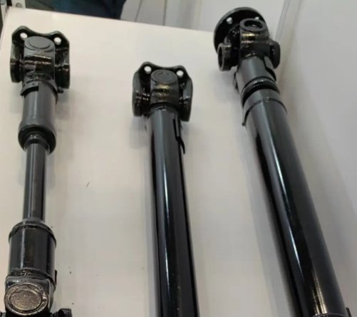
- Automotive and off-highway driveline components
- Packaging, printing and textile machinery
- Robotics, automation and linear motion systems
- Food processing and washdown equipment
Summary
A bearing shaft is a critical mechanical component that directly affects bearing life, vibration, temperature, sealing performance and equipment reliability. The most important specification factors are material, heat treatment, bearing fit, journal tolerance, runout, surface roughness, shoulder geometry and inspection method.
For reliable performance, bearing shaft design should connect the bearing manufacturer’s fit recommendations with real operating conditions such as load direction, speed, duty cycle, environment and assembly process. For purchasing, drawings should define measurable requirements and request inspection data for critical journals and functional datums.