Metal machining for robotics and industrial automation covers the precision manufacturing of structural, motion-control, tooling, and end-of-arm components used in robotic cells, automated assembly lines, packaging systems, semiconductor equipment, inspection machinery, and custom industrial machines. These parts must do more than fit together: they must maintain alignment, resist vibration, support repeatable motion, and survive continuous-duty production environments.
In robotics and automation, machined metal parts directly affect accuracy, payload capacity, cycle time, uptime, and long-term repeatability. For engineers, buyers, and machine builders, choosing the right machining process, material, tolerance strategy, and inspection method can reduce commissioning risk and prevent costly field failures.
What Metal Machining Means in Robotics and Automation
Metal machining is a subtractive manufacturing process that removes material from billets, castings, forgings, extrusions, or plate stock to create parts with controlled geometry, surface finish, and dimensional accuracy. In robotics and automation, common machining methods include CNC milling, CNC turning, 5-axis machining, wire EDM, sinker EDM, surface grinding, cylindrical grinding, honing, tapping, reaming, boring, and precision deburring.
Unlike decorative or low-load metal parts, robotic and automation components often function as part of a motion system. A machined bracket, gearbox housing, gripper finger, actuator mount, or linear rail base can influence stack-up error, servo tuning, vibration, and repeatable positioning.
Typical applications
- Robotic arm joints, wrist adapters, servo motor housings, and gearbox plates
- End-of-arm tooling, gripper fingers, vacuum cup manifolds, and quick-change plates
- Linear motion bases, actuator brackets, ball screw supports, and rail mounting plates
- Machine frames, precision fixtures, nests, locating blocks, and inspection gauges
- Conveyor components, indexing plates, rotary tables, and packaging machine parts
- Sensor mounts, camera brackets, laser alignment components, and metrology fixtures
Why Robotics Parts Are Different from General Machined Parts
Robotics and automation parts are usually judged by function over appearance. A part may look acceptable but still fail if it introduces angular error, insufficient stiffness, thread pullout, poor bearing alignment, or uncontrolled burrs near cables, seals, or moving elements.
A practical engineering rule is to tolerance only what controls motion, alignment, load transfer, sealing, or assembly repeatability. Over-tolerancing every dimension increases machining cost, inspection time, and lead time without improving machine performance.
Critical performance requirements
- Repeatability: robotic fixtures and end effectors must return to the same position across thousands or millions of cycles.
- Stiffness-to-weight ratio: lightweight parts improve robot acceleration, while insufficient stiffness causes deflection and vibration.
- Positional accuracy: dowel holes, bearing bores, rail seats, and motor pilot diameters often require tight GD&T control.
- Thermal stability: automation systems may operate near motors, weld cells, curing ovens, or coolant systems.
- Wear resistance: locating nests, pins, sliding contact surfaces, and gripper jaws may require hardened steel, coatings, or replaceable inserts.
- Clean assembly: burrs, chips, and sharp edges can damage cables, pneumatic lines, seals, or operators' hands.
Engineering note: why stiffness matters in robotic tooling
End-of-arm tooling mounted far from the robot wrist behaves like a cantilever. Even a small amount of deflection at the tool plate can create several tenths of a millimeter of error at the gripper tip. For high-speed pick-and-place, welding, dispensing, and inspection applications, part stiffness, mass distribution, and mounting flatness should be considered during the design phase, not corrected after commissioning.
Key Machined Components for Robotics and Industrial Automation
Metal machined parts appear throughout a robotic cell. The most critical components are usually those that establish reference geometry, carry dynamic loads, or interface with purchased components such as motors, bearings, gearboxes, sensors, and linear guides.
Robot arm and motion system components
Robot joints, adapter plates, harmonic drive housings, bearing carriers, shaft couplings, and servo mounts require concentricity, flatness, and perpendicularity control. Motor pilots, bolt circles, dowel locations, and bearing seats are often more important than overall outside dimensions.
End-of-arm tooling and gripper parts
End effectors must balance strength, weight, and accessibility. CNC-machined aluminum is common for tool plates and manifolds, while hardened steel or stainless steel is used for gripper fingers, wear pads, and locating surfaces. For collaborative robots, lightweight machining and rounded edges also help reduce inertia and improve operator safety.
Fixtures, nests, and locating hardware
Automation fixtures must repeatedly locate workpieces despite part variation, debris, and production wear. Machined fixture plates, rest pads, locating pins, clamps, and nests are frequently designed with replaceable wear components to reduce maintenance cost.
Machine frames and precision bases
Large aluminum tooling plates, steel weldments, and cast iron bases often require face milling, stress relief, grinding, boring, or re-machining after welding. The goal is not only dimensional accuracy but also geometric stability over time.
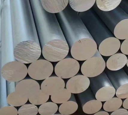
Materials Used for Robotic and Automation Machined Parts
Material selection depends on load, weight, corrosion exposure, wear, thermal expansion, magnetic behavior, electrical conductivity, and cost. In many automation projects, material choice also affects lead time because common alloys are easier to source in plate, bar, tube, and extrusion formats.
Aluminum alloys are widely used where low mass, fast machining, and good corrosion resistance are more valuable than maximum wear resistance. Steel and stainless steel are preferred when high strength, threaded durability, impact resistance, or wear life is required.
| Material | Common Grades | Best Uses in Robotics and Automation | Engineering Notes |
|---|---|---|---|
| Aluminum | 6061-T6, 6082, 7075-T6, MIC-6 cast plate | Robot tool plates, brackets, manifolds, sensor mounts, lightweight fixtures | Excellent machinability; anodizing improves corrosion and wear resistance; 7075 offers higher strength than 6061. |
| Carbon Steel | 1018, 1045, A36 | Machine frames, shafts, fixture bases, structural brackets | Good strength and cost efficiency; may require plating, black oxide, paint, or oil for corrosion protection. |
| Alloy Steel | 4140, 4340 | High-load pins, shafts, coupling parts, wear components | Can be heat treated for strength and fatigue resistance; machining strategy changes after hardening. |
| Stainless Steel | 304, 316, 17-4 PH | Food automation, washdown equipment, medical devices, corrosion-resistant grippers | 316 improves corrosion resistance; 17-4 PH provides high strength after precipitation hardening. |
| Tool Steel | A2, D2, O1, S7 | Locating inserts, wear pads, forming tools, gripper contact points | High wear resistance; often machined soft, heat treated, then ground to final tolerance. |
| Titanium | Grade 2, Grade 5 Ti-6Al-4V | Lightweight high-strength parts, aerospace automation, corrosion-resistant tooling | High strength-to-weight ratio but more expensive and slower to machine than aluminum. |
| Copper and Brass | C110, C360 | Electrical contacts, heat transfer components, bushings, pneumatic fittings | Copper offers high conductivity; brass is easier to machine and useful for low-friction components. |
Surface Finishes and Treatments
Surface treatment is not only cosmetic in automation. It can improve corrosion resistance, reduce glare for vision systems, prevent galling, increase wear life, and identify replaceable tooling components.
Common finishes
- As-machined: suitable for internal plates, brackets, and non-cosmetic components when corrosion is not a major issue.
- Anodizing: common for aluminum EOAT, robot plates, and sensor mounts; hardcoat anodizing improves wear resistance.
- Black oxide: used on steel parts for mild corrosion resistance and reduced reflectivity.
- Electroless nickel plating: provides uniform corrosion resistance and is useful for complex geometries.
- Zinc plating: cost-effective corrosion protection for steel components.
- Passivation: improves corrosion resistance of stainless steel by removing free iron from the surface.
- Nitriding and carburizing: increase surface hardness for wear-critical steel parts.
- Grinding and lapping: used for flatness, parallelism, and controlled surface finish on precision interfaces.
Finish selection tip for machine vision systems
Bright aluminum, polished stainless steel, and plated surfaces can create reflections that interfere with cameras, lasers, and optical sensors. Matte anodizing, bead blasting before anodizing, black oxide, or controlled surface texture may improve image stability in automated inspection cells.
Core Machining Processes for Automation Components
The best process depends on geometry, production volume, tolerance requirements, and material. Many robotic components require multiple operations, such as milling, turning, heat treatment, grinding, and final inspection.
CNC milling
CNC milling is used for plates, brackets, housings, fixtures, manifolds, pockets, slots, and complex 3D contours. 3-axis milling is cost-effective for prismatic parts, while 4-axis and 5-axis milling reduce setups and improve access to angled features.
CNC turning
CNC turning is used for shafts, spacers, bushings, rollers, pins, couplings, sleeves, and circular housings. Live-tool turning centers can mill flats, keyways, cross holes, and bolt patterns without moving the part to a separate mill.
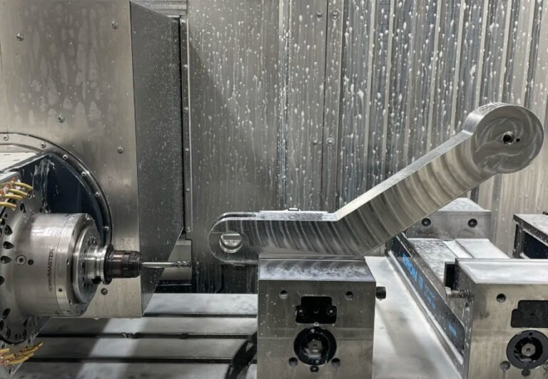
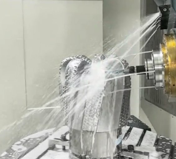
5-axis machining
5-axis CNC machining is valuable for robotic wrist adapters, lightweight brackets, contoured gripper parts, impeller-like automation components, and aerospace automation tooling. It can reduce cumulative setup error by machining multiple faces in one clamping.
EDM machining
Wire EDM and sinker EDM are used for hardened steel, sharp internal corners, intricate profiles, and precise slots. EDM is common for tool steel inserts, locating details, dies, and wear components that are difficult to mill after heat treatment.
Grinding and precision finishing
Surface grinding, cylindrical grinding, jig grinding, and honing are used when milling or turning cannot reliably achieve the required flatness, roundness, straightness, surface finish, or bearing fit.
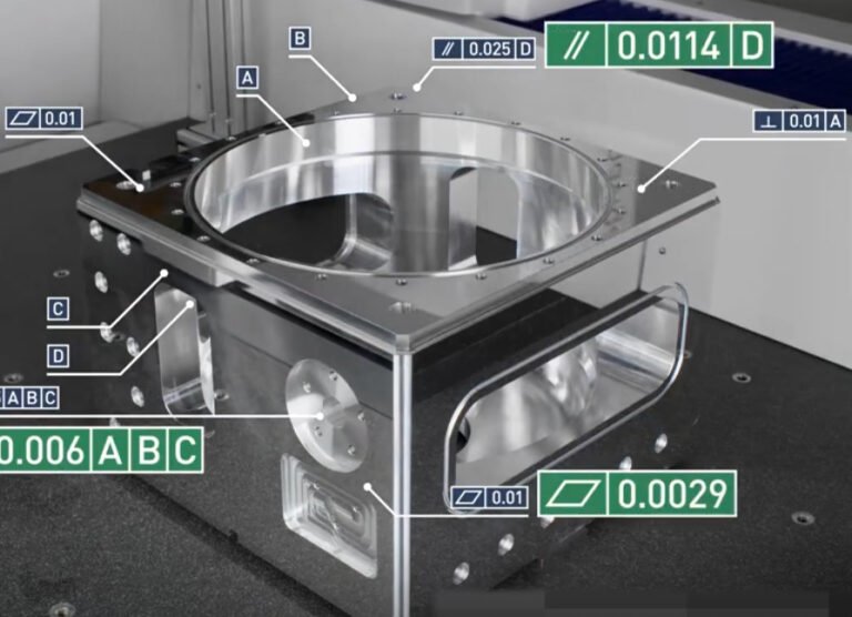
Tolerances, GD&T, and Inspection Requirements
Tolerances in robotic and automation machining should be based on function. A general profile or block dimension may only need a standard machining tolerance, while bearing bores, dowel holes, datum faces, and rail mounting surfaces may require much tighter control.
True position, flatness, parallelism, perpendicularity, concentricity, runout, and profile tolerances are often more important than simple plus/minus dimensions. GD&T helps define how a part functions in an assembly and how it should be inspected.
| Feature Type | Typical Functional Concern | Common Control Method |
|---|---|---|
| Dowel holes | Repeatable fixture or plate location | Reaming, boring, true position to datums |
| Bearing bores | Fit, alignment, rotation quality | Boring, interpolation, grinding, cylindricity, diameter tolerance |
| Motor pilot diameters | Concentricity between motor and driven component | Diameter tolerance, runout, perpendicularity to mounting face |
| Linear rail mounting faces | Straight-line motion and rail preload | Flatness, parallelism, surface finish, dowel reference edge |
| Fixture nests | Part location under repeated loading | Profile tolerance, hard inserts, replaceable pads |
| Threaded holes | Assembly strength and serviceability | Thread class, depth control, helicoil inserts, thread gauges |
Inspection tools commonly used
- Coordinate measuring machines for datum-based dimensional reports
- Height gauges and granite surface plates for flatness and location checks
- Bore gauges, pin gauges, plug gauges, and thread gauges
- Optical comparators and vision systems for profiles and small features
- Surface roughness testers for sealing, sliding, or bearing surfaces
- Runout indicators and rotary inspection fixtures for shafts and circular parts
- Material certificates, hardness testing, and coating thickness measurement when specified
First article inspection is especially useful for automation parts with tight datum structures, multiple setups, or parts that will be repeated in production builds. It helps catch drawing interpretation issues before a full batch is machined.
Example tolerance strategy for a robot adapter plate
A robot adapter plate may use a broad general tolerance for external edges, tighter flatness on the robot mounting face, true position on dowel holes, and perpendicularity between the mounting face and a machined pilot diameter. This approach controls the functional interfaces without making every cosmetic edge expensive to machine and inspect.
Design for Manufacturability Guidelines
Design for manufacturability, or DFM, reduces machining time, scrap risk, inspection ambiguity, and assembly problems. For robotic and automation components, the best DFM decisions are made before procurement, not after the machine shop identifies conflicts in the model or drawing.
Good DFM for automation parts balances precision, stiffness, weight, serviceability, and manufacturing cost. The following guidelines apply to many CNC-machined robotic components.
Practical DFM recommendations
- Use standard stock thicknesses and bar sizes where possible to reduce material cost and lead time.
- Add internal corner radii that match available end mills instead of specifying sharp milled corners.
- Avoid deep narrow pockets unless weight reduction or clearance is functionally necessary.
- Specify critical datums clearly on drawings, especially for multi-face and multi-setup parts.
- Use dowel pins or precision shoulders for repeatable location instead of relying only on clearance bolts.
- Design replaceable wear pads or inserts for high-contact fixture and gripper surfaces.
- Keep threaded holes deep enough for load but not unnecessarily deep, especially in stainless steel or hard materials.
- Separate cosmetic requirements from functional surface finish requirements.
- Use symmetrical lightening patterns when weight reduction is needed to avoid distortion and imbalance.
- Consider stress relief for large aluminum plates, steel weldments, and heavily machined parts.
Engineering Case Results and Real Production Issues
Robotics machining problems are often discovered during assembly or commissioning rather than at the machine shop. The examples below reflect common engineering outcomes in automation projects and show how manufacturing decisions can affect measurable performance.
Case 1: Lightweight end-effector plate for faster robot motion
A pick-and-place end-effector plate was redesigned from a thick rectangular aluminum plate to a pocketed 6061-T6 structure with ribbed reinforcement. The machined part maintained the same robot and gripper interfaces but removed non-load-bearing material.
- Mass reduction: approximately 32%
- Robot acceleration limit improved without increasing servo fault events
- Cycle time reduction: about 0.4 seconds on a short transfer motion
- Functional surfaces retained tight flatness and dowel-hole position control
Case 2: Fixture repeatability improved by controlling datum features
A welding fixture showed inconsistent part location after several weeks of production. The original machined plate used clearance holes only, and locating edges were not defined as datums. The revised design added hardened dowel pins, replaceable rest pads, and true position callouts for locating holes.
- Measured part location variation reduced from roughly 0.35 mm to under 0.08 mm
- Fixture maintenance became faster because wear pads were replaceable
- Weld rework decreased due to more consistent joint alignment
Case 3: Linear rail base corrected with machining sequence changes
A long aluminum rail base distorted after aggressive pocket milling. The solution was to use stress-relieved plate, rough machine both sides, allow stabilization, then finish machine the datum face and rail reference edge in a controlled setup.
- Rail mounting face flatness improved from about 0.18 mm to 0.04 mm over the measured length
- Carriage preload became consistent after assembly
- Servo tuning required less compensation for friction variation
Case note: many automation failures are not caused by the nominal CAD shape, but by uncontrolled datums, burrs, distortion, stack-up error, or insufficient inspection of functional interfaces.
Sourcing and Cost Drivers for Machined Robotics Parts
Buyers and engineers should evaluate machine shops based on capability, quality systems, communication, and experience with functional parts, not only quoted unit price. A lower-cost part can become expensive if it causes assembly delays, rework, line downtime, or repeated engineering changes.
Total cost should include machining, material, finishing, inspection, documentation, packaging, revision control, and the cost of downtime if a part fails in production.
Main cost drivers
- Material: aluminum is generally faster to machine than stainless steel, titanium, or hardened tool steel.
- Complexity: undercuts, multiple angled faces, deep pockets, and tight internal radii increase setup and tooling time.
- Tolerance: tight tolerances require slower machining, stable workholding, inspection, and sometimes grinding.
- Surface finish: cosmetic finishes, anodizing, plating, passivation, and polishing add process steps.
- Quantity: prototypes have higher setup cost per part, while production batches benefit from fixture amortization.
- Lead time: expedited machining may require premium scheduling, material substitution, or split operations.
- Documentation: CMM reports, material certifications, plating certificates, and first article reports add value and cost.
What engineers and buyers should provide
- 3D CAD model in STEP, Parasolid, or native CAD format
- 2D drawing with critical tolerances, datums, thread notes, and finish requirements
- Material grade, temper, heat treatment, and acceptable substitutes if any
- Surface treatment specification, color, masking areas, and coating thickness if needed
- Inspection requirements, including which dimensions require reporting
- Expected production quantity, prototype quantity, and revision status
- Assembly context for critical interfaces, especially bearings, rails, motors, and sensors
Quality Control for High-Reliability Automation Components
Quality control for robotics machining should be built around functional risk. Not every feature requires a full dimensional report, but critical-to-function dimensions should be verified with suitable equipment and documented when required.
Recommended quality practices
- Review drawings for tolerance conflicts, missing datums, and unclear finish requirements before machining.
- Use in-process inspection for critical bores, dowel holes, and datum surfaces instead of waiting until final inspection.
- Control burrs on cable paths, pneumatic channels, vacuum ports, and gripper contact surfaces.
- Protect precision faces during finishing, transport, and assembly.
- Maintain revision control for repeat orders and spare parts.
- Use serialized or batch-traceable parts for safety-critical or regulated automation systems.
- Confirm coating buildup when plated or anodized features affect fits.
For parts used in food processing, medical automation, aerospace tooling, battery manufacturing, or semiconductor equipment, additional documentation may be needed, such as material traceability, RoHS or REACH compliance, clean packaging, passivation records, or controlled cleaning procedures.
Conclusion: Machining Strategy Determines Automation Performance
Metal machining for robotics and industrial automation is a precision engineering discipline that connects CAD design, material science, CNC manufacturing, GD&T, surface finishing, and inspection. The most successful machined parts are not simply accurate in isolation; they support stable motion, repeatable assembly, predictable maintenance, and reliable production.
Buyer takeaway: the best machined automation components are designed around functional interfaces, manufactured with stable processes, and inspected against the features that control real machine performance. When material, tolerance, finish, and inspection choices align with the actual application, robotic systems become easier to assemble, faster to commission, and more reliable in production.