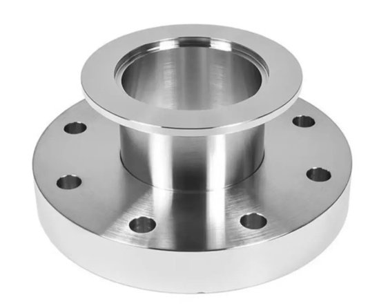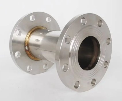
Lap Joint Flanges are loose-type pipe flanges used together with a stub end, also called a lap joint stub end or lapped pipe end. Unlike weld neck or slip-on flanges, the flange itself is not welded directly to the pipe and does not normally contact the process fluid. The stub end is welded to the pipe, while the lap joint flange rotates freely behind the stub end lap to simplify bolt alignment during installation.
This flange design is widely specified for stainless steel, duplex stainless steel, nickel alloy, titanium, lined pipe, and other piping systems where frequent dismantling, corrosion allowance, material economy, or field alignment is important. It is commonly used in chemical processing, water treatment, marine piping, pharmaceutical plants, food-grade utilities, offshore modules, and non-critical utility lines requiring repeated inspection or cleaning.
What Is a Lap Joint Flange?
A lap joint flange is a two-part connection consisting of a stub end and a loose flange. The stub end provides the sealing surface and is welded to the pipe. The loose flange provides the bolting load and mechanical clamping force. Because the flange can rotate before bolting, installers can align bolt holes even when pipe spools are slightly misoriented.
In most applications, the stub end material matches the pipe and fluid requirements, while the backing flange may be made from carbon steel or another cost-effective material because it is isolated from the process medium. This makes lap joint construction especially valuable in expensive alloy piping systems.
Key Advantages of Lap Joint Flanges
- Easy bolt-hole alignment: the flange rotates freely, reducing installation time on prefabricated spools and field-fit joints.
- Lower alloy cost: the wetted stub end can be stainless steel, duplex, or nickel alloy, while the loose backing flange can often be carbon steel.
- Reusable flange ring: when the stub end or pipe section is replaced, the backing flange may be reused if it remains dimensionally and mechanically acceptable.
- Convenient dismantling: suitable for systems requiring periodic cleaning, inspection, or equipment removal.
- Good for large-diameter pipework: easier assembly on site where rotating a heavy pipe spool is impractical.
Common Types and Configurations
ASME Lap Joint Flanges
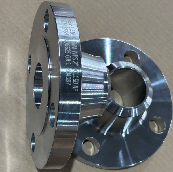
ASME lap joint flanges are commonly manufactured to ASME B16.5 for NPS 1/2 to NPS 24 and ASME B16.47 Series A or Series B for larger sizes. Typical pressure ratings include Class 150 to Class 2500, depending on material grade, temperature, and design code.
EN and DIN Lap Joint Flanges
European loose flanges are often supplied to EN 1092-1, DIN 2641, DIN 2642, DIN 2655, DIN 2656, or project-specific drawings. Standard pressure designations include EN 1092-1 PN 6 to PN 100, with face dimensions selected according to the gasket and stub end standard.
Short Pattern and Long Pattern Stub End Assemblies
Short pattern stub ends are frequently used in lower-pressure or compact piping layouts, while long pattern stub ends provide a longer neck and are commonly selected for ASME B16.9 dimensional compatibility. The flange bore must be compatible with the stub end radius to prevent interference during assembly.
Carbon Steel, Stainless Steel, Duplex, and Alloy Options
Lap joint flanges can be produced from ASTM A105, A350 LF2, A182 F304, F316, F321, F347, F51, F53, F55, alloy steel, and nickel alloy materials. For seawater, chloride, sour gas, or acidic services, engineers typically select the stub end based on corrosion resistance and the backing flange based on mechanical load and environmental exposure.
Technical Specifications
| Item | Typical Options | Engineering Notes |
|---|---|---|
| Standards | ASME B16.5, ASME B16.47, EN 1092-1, DIN, JIS, MSS SP-43 | Match flange, stub end, gasket, and bolt standards as one system. |
| Size Range | NPS 1/2 to NPS 60, DN15 to DN1500 or custom | Large-diameter sizes may require forged, rolled, or welded ring construction depending on code. |
| Pressure Rating | Class 150, 300, 600, 900, 1500, 2500; PN 6 to PN 100 | Final rating depends on material, temperature, gasket type, and design code. |
| Face Type | Lap joint face, flat face interface with stub end lap | The gasket sealing surface is normally provided by the stub end, not the loose flange ring. |
| Manufacturing | Forged, machined, normalized, quenched and tempered, solution annealed | Heat treatment follows material grade and service requirements. |
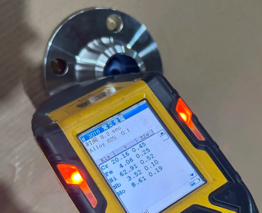
| Inspection | Dimensional check, PMI, UT, MT, PT, hardness, MTC EN 10204 3.1 or 3.2 | Critical projects may require third-party inspection and full heat-number traceability. |
How Lap Joint Flanges Solve Real Engineering Problems
In prefabricated piping, bolt-hole mismatch is a frequent field problem. With weld neck or slip-on flanges, correcting misalignment may require cutting, rotating, and rewelding the spool. A lap joint arrangement allows the flange ring to rotate independently, which can reduce rework during installation.
In one stainless process-water project, the piping contractor replaced fixed stainless steel flanges with 316L stub ends and carbon steel lap joint backing flanges on DN200 lines. The result was a measured reduction of approximately 28% in flange-related material cost and a decrease of about 35% in flange alignment rework hours during module assembly. Actual savings depend on alloy grade, pipe size, labor rate, and inspection scope.
For corrosion-resistant alloy systems, the cost difference becomes more significant. On high-nickel alloy pipework, using alloy stub ends with coated carbon steel backing flanges can reduce flange assembly cost by 20% to 45% compared with full-alloy weld neck flanges, while keeping the wetted surface compatible with the process fluid.
Manufacturing and Machining Quality
Reliable lap joint flange performance depends on accurate machining, controlled bore dimensions, correct bolt circle geometry, and smooth contact surfaces. During production, forged blanks are cut, heat treated when required, rough machined, finish machined, drilled, deburred, marked, and inspected before packing.
Critical manufacturing controls include surface finish and bolt-hole alignment, flange outside diameter, bolt circle diameter, thickness, hub dimensions, bore clearance, and back-face flatness. If the flange bore is too small or the radius is incompatible with the stub end, the flange may not seat correctly behind the lap, causing uneven loading and leakage risk.
For stainless steel and duplex materials, machining coolant control, pickling, passivation, and contamination prevention are important. Carbon steel backing flanges can be supplied with black paint, anti-rust oil, hot-dip galvanizing, zinc-rich primer, epoxy coating, or project-specified coating systems for marine or outdoor service.
Material Selection for Buyers and Engineers
The best lap joint flange specification balances corrosion resistance, mechanical strength, operating temperature, inspection level, and total installed cost. Procurement teams should avoid selecting the flange ring alone without confirming the stub end standard, gasket type, bolt material, and pipe schedule.
- For stainless process piping: 304/304L or 316/316L stub ends with carbon steel or stainless backing flanges are common.
- For chloride environments: duplex F51, super duplex F53/F55, or suitable nickel alloys may be required for the wetted stub end.
- For low-temperature service: A350 LF2 or impact-tested stainless grades may be specified according to design code.
- For lined piping: confirm lap dimensions, liner thickness, gasket compression, and flange bore clearance.
- For marine use: coating selection for backing flanges is often as important as base material selection.
Standards and Compliance
Lap joint flanges are typically supplied according to recognized piping flange standards and project specifications. For ASME systems, dimensional requirements are commonly based on ASME B16.5 or ASME B16.47. Stub ends are frequently produced to ASME B16.9 or MSS SP-43, depending on wall thickness, pattern, and service condition.
Documentation may include material test certificates, heat treatment records, dimensional reports, positive material identification, non-destructive examination reports, coating reports, and packing lists. For regulated projects, material traceability from raw material to finished flange should be maintained through heat number marking and certificate control.
Recommended ordering information
- Standard: ASME B16.5, ASME B16.47, EN 1092-1, DIN, JIS, or drawing
- Size: NPS/DN and pipe schedule or wall thickness
- Pressure class: Class, PN, or project rating
- Material grade: flange ring and stub end material if supplied as an assembly
- Stub end type: short pattern, long pattern, Type A, Type B, or Type C where applicable
- Coating or surface treatment: oil, paint, galvanizing, epoxy, pickling, passivation
- Inspection level: MTC 3.1, 3.2, PMI, NDE, impact test, hardness test
- Quantity, delivery requirement, and packing method
Installation Considerations
Correct installation is essential for sealing reliability. Before assembly, installers should confirm that the stub end lap surface is clean, the gasket is compatible with the fluid and temperature, the flange ring rotates freely, and bolt holes are aligned without forcing the pipe into position.
Bolts should be tightened using a cross-pattern sequence and controlled torque or tensioning method when specified. Uneven tightening can distort the stub end lap or overload part of the gasket. For large-diameter or thin-wall piping, flange parallelism and pipe support must be checked to avoid bending loads at the joint.
Common installation issues to check
- Wrong stub end radius causing interference with the flange bore
- Backing flange material not suitable for external corrosion exposure
- Gasket selected for a raised-face flange instead of the actual stub end sealing geometry
- Pipe spool weight not supported, causing rotation or bending at the joint
- Incorrect bolt length due to combined stub end lap and flange thickness
Lap Joint Flange vs. Weld Neck and Slip-On Flange
| Feature | Lap Joint Flange | Weld Neck Flange | Slip-On Flange |
|---|---|---|---|
| Pipe Connection | Used with welded stub end; flange remains loose | Butt welded directly to pipe | Fillet welded to pipe |
| Bolt Alignment | Excellent due to rotating flange | Fixed after welding | Fixed after welding |
| Fluid Contact | Stub end contacts fluid; flange ring usually does not | Flange bore contacts fluid | Flange bore may contact fluid |
| Material Economy | High for expensive alloy systems | Lower when full alloy flange is required | Moderate |
| Mechanical Rigidity | Lower than weld neck under severe bending or fatigue | Excellent | Moderate |
| Best Use | Corrosive service, dismantling, alignment-sensitive piping | High-pressure, high-temperature, critical cyclic service | General low-to-medium pressure utility service |
When Not to Use Lap Joint Flanges
Lap joint flanges are not the best choice for every service. They are generally less rigid than weld neck flanges and may not be preferred for severe cyclic loading, high external bending moments, extreme vibration, or highly critical high-pressure systems unless the design has been verified by the responsible engineer.
In high-temperature service, differential thermal expansion between the stub end and backing flange should be considered. In outdoor or marine environments, carbon steel backing flanges require appropriate coating or corrosion protection even though they are not in contact with the process fluid.
Engineering review points before approval
- Design pressure and temperature rating of the complete flange assembly
- Compatibility between flange standard and stub end standard
- Gasket seating width and required bolt load
- External loads from pipe supports, thermal expansion, vibration, or equipment nozzles
- Corrosion risk on the non-wetted backing flange
- Project code requirements such as ASME B31.3, ASME B31.1, EN 13480, or client specifications
Product Summary
Lap joint flanges provide a practical and cost-efficient connection for piping systems that require easy alignment, frequent dismantling, or corrosion-resistant wetted components. When properly matched with the correct stub end, gasket, bolts, material grade, and inspection requirements, they can reduce installation rework and lower total alloy material cost while maintaining reliable flange joint performance.
For accurate procurement, specify the flange standard, size, pressure class, material, stub end type, pipe schedule, coating, inspection level, and documentation requirements. This ensures that the supplied lap joint flange assembly fits the piping design and performs as intended in field operation.