Pipe Flanges are mechanical connectors used to join pipes, valves, pumps, pressure vessels and process equipment in systems that require secure assembly, inspection access and maintainability. A properly specified pipe flange provides bolted joint integrity, gasket compression and alignment control under pressure, temperature, vibration and corrosive service conditions.
Our flanges are manufactured for oil and gas, chemical processing, power generation, shipbuilding, water treatment, HVAC, mining, food processing and general industrial piping. Standard and customized options are available according to ASME, EN, DIN, JIS, BS, MSS and project-specific drawings.
Product Overview and Engineering Function
A pipe flange connection normally consists of two flanges, a gasket, bolts, nuts and the connected pipe or equipment nozzle. The flange transmits bolting load to the gasket and maintains sealing stress during operation. For pressure piping, flange selection must match the design pressure, design temperature, pipe schedule, fluid category and applicable code.
- Connection methods: butt welding, socket welding, threaded connection, lap joint and loose backing configuration.
- Common sealing faces: raised face, flat face, ring type joint, tongue and groove, male and female.
- Nominal sizes: commonly from 1/2 inch to 60 inch, with larger custom sizes available by drawing.
- Pressure ratings: Class 150 to Class 2500, PN6 to PN400, and JIS 5K to 63K depending on standard.
- Manufacturing routes: forging, plate cutting, rolling, heat treatment, CNC machining, drilling, facing and coating.
Common Types of Pipe Flanges
Different flange designs solve different installation and operating problems. The correct type depends on pressure class, pipe wall thickness, welding access, maintenance frequency, alignment tolerance and cost target.
| Flange Type | Typical Use | Engineering Notes |
|---|---|---|
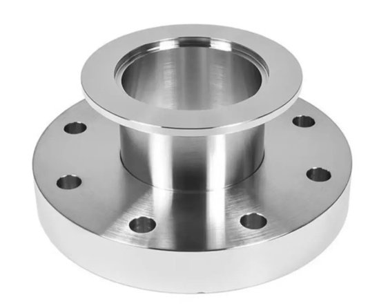
| Weld Neck Flange | High-pressure, high-temperature and cyclic loading service | Long tapered hub reduces stress concentration and allows full penetration butt welding. |
| Slip On Flange | Low to medium pressure utility piping | Easy alignment and economical installation; generally requires fillet welds inside and outside. |
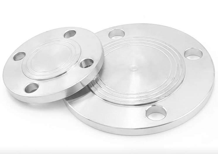
| Blind Flange | Closing pipe ends, valves and pressure vessel openings | Designed to resist pressure load without a bore; useful for inspection and future expansion points. |
| Socket Weld Flange | Small-bore high-pressure piping | Provides good fatigue strength when properly welded; commonly used in chemical and steam lines. |
| Threaded Flange | Systems where welding is not preferred | Suitable for low-pressure or hazardous welding-restricted environments; thread sealing must be controlled. |
| Lap Joint Flange | Systems requiring frequent dismantling or expensive alloy wetted parts | Used with stub end; backing flange can rotate for bolt alignment and may be made from lower-cost material. |
| Orifice Flange | Flow measurement pipelines | Includes pressure tap holes and is used with orifice plates for differential pressure measurement. |
| Reducing Flange | Pipe size transition without reducers | Connects different nominal pipe sizes where space is limited. |
When should a weld neck flange be selected?
Weld neck flanges are preferred for severe service, such as steam, hydrocarbons, thermal cycling, vibration and high-pressure pipelines. The butt-welded neck improves load transition from pipe to flange and reduces localized stress compared with simpler flange types.
Standards, Pressure Ratings and Dimensions
Pipe Flanges can be supplied to international standards or engineered drawings. Dimensional compliance is critical because bolt hole diameter, bolt circle diameter, flange thickness, hub geometry and facing height directly affect fit-up and sealing performance.
| Standard | Common Rating System | Typical Markets |
|---|---|---|
| ASME B16.5 | Class 150, 300, 400, 600, 900, 1500, 2500 | Oil and gas, petrochemical, power, process industries |
| ASME B16.47 Series A/B | Large diameter Class 75 to Class 900 | Large pipelines, terminals, water systems, pressure equipment |
| EN 1092-1 | PN6, PN10, PN16, PN25, PN40 and higher | European industrial piping and infrastructure |
| DIN Flanges | PN-based ratings | Legacy European systems and equipment replacement |
| JIS B2220 | 5K, 10K, 16K, 20K, 30K, 40K, 63K | Japanese and Asian industrial projects |
| MSS SP-44 | Steel pipeline flanges | Transmission pipelines and heavy-duty piping |
Pressure rating is not a fixed pressure value for all temperatures. For example, an ASME Class 300 carbon steel flange can carry higher pressure at ambient temperature than at elevated temperature. The final allowable pressure must be verified using the relevant standard pressure-temperature table and material group.
Materials and Service Compatibility
Flange material affects strength, corrosion resistance, weldability and lifecycle cost. Material selection should consider fluid chemistry, chloride content, operating temperature, galvanic compatibility and welding procedure requirements.
| Material Category | Common Grades | Suitable Applications |
|---|---|---|
| Carbon Steel | ASTM A105, A350 LF2, A694 F52/F60/F65 | Oil, gas, water, steam, general industrial piping |
| Stainless Steel | ASTM A182 F304/304L, F316/316L, F321, F347 | Corrosive fluids, food processing, chemical and marine environments |
| Duplex Stainless Steel | F51, F53, F55 | Chloride service, offshore systems, seawater and high-strength applications |
| Alloy Steel | F11, F22, F5, F9, F91 | High-temperature steam, refinery units, power generation |
| Nickel Alloy | Inconel, Incoloy, Hastelloy, Monel grades | Severe corrosion, high temperature and specialty chemical service |
What is the difference between ASTM A105 and ASTM A182 F316L flanges?
ASTM A105 is a forged carbon steel grade commonly used for general pressure piping. ASTM A182 F316L is a stainless steel grade with molybdenum content for improved corrosion resistance, especially in chloride-containing or chemical environments. F316L is usually more expensive but can reduce corrosion-related replacement costs.
Facing, Gasket Surface and Sealing Performance
Flange facing determines gasket seating behavior and leakage risk. A raised face is common for ASME flanges, flat face is often used with cast iron or low-pressure equipment, and RTJ facing is selected for high-pressure or critical hydrocarbon service.
- RF - Raised Face: widely used with spiral wound, non-asbestos, graphite and PTFE gaskets.
- FF - Flat Face: often matched with full-face gaskets to avoid bending stress on brittle equipment flanges.
- RTJ - Ring Type Joint: metal-to-metal sealing using oval or octagonal rings for high-pressure applications.
- Tongue and Groove: improves gasket confinement and alignment for selected process services.
- Male and Female: supports controlled gasket positioning and reduced blowout risk.
Surface finish is also important. For many spiral wound gasket applications, a serrated concentric or spiral finish in the approximate range of 125 to 250 AARH is commonly specified, subject to gasket manufacturer and project requirements.
Manufacturing and Machining Capabilities
Industrial pipe flanges require controlled forming, heat treatment and machining. Manufacturing quality influences bolt preload retention, face flatness, weld-end integrity and dimensional interchangeability.
- Raw material inspection, including grade verification and heat number traceability.
- Forging or plate processing according to product type, diameter and pressure class.
- Normalizing, annealing, solution treatment, quenching or tempering as required by material specification.
- CNC turning of outside diameter, bore, hub, thickness, raised face and gasket seating surface.
- Drilling of bolt holes with controlled bolt circle diameter and angular spacing.
- Threading, beveling, serration machining, RTJ groove machining or custom facing.
- Surface protection such as anti-rust oil, black painting, yellow painting, zinc coating, hot-dip galvanizing or epoxy coating.
For engineered orders, we can produce flanges according to drawings with requirements for special bore, non-standard thickness, long weld neck geometry, coating system, low-temperature impact testing, NACE MR0175 / ISO 15156 compliance or sour service documentation.
Quality Control, Testing and Documentation
A flange may look simple, but small dimensional deviations can create major field problems. Quality control focuses on dimensional accuracy, material conformity, sealing face finish and traceability.
| Inspection Item | Purpose | Typical Output |
|---|---|---|
| Dimensional Inspection | Verify OD, ID, PCD, bolt holes, thickness, hub and facing | Inspection report against standard or drawing |
| Material Test | Confirm chemical composition and mechanical properties | EN 10204 3.1 material certificate |
| PMI Testing | Prevent stainless steel and alloy grade mix-up | Positive material identification report |
| NDT | Detect surface or internal defects | UT, MT, PT or RT reports when specified |
| Hardness Test | Check heat treatment and sour service suitability | Hardness records by batch or item |
| Visual and Surface Inspection | Confirm finish, marking, coating and sealing face condition | Final QC checklist and photos if required |
Which documents are commonly requested by buyers and project engineers?
Common documents include material test certificates, dimensional inspection reports, heat treatment records, PMI reports, NDT reports, coating reports, certificate of origin, packing list and compliance declarations for the specified standard. For critical projects, ITP and third-party inspection can also be arranged.
Real Engineering Problems Solved by Correct Flange Specification
Many flange failures are not caused by the flange body alone, but by incorrect matching of flange type, gasket, bolting, tightening procedure and operating condition. Field experience shows that precise specification can reduce leakage, rework and shutdown risk.
- Leakage after hydrotest: often related to damaged gasket face, wrong gasket type, uneven bolt tightening or poor flange alignment. Controlled surface finish and dimensional inspection help reduce this risk.
- Bolt hole misalignment: usually caused by mixed standards or inaccurate drilling. Confirming ASME, EN, JIS or DIN dimensions before production avoids site modification.
- Corrosion around flange joints: can result from unsuitable material or coating. Stainless steel, duplex stainless steel, galvanizing or epoxy coating may improve service life depending on environment.
- Weld cracking or fit-up issues: may occur when bore, bevel, pipe schedule or weld-end preparation is not specified. Matching flange bore to pipe schedule is essential for weld neck flanges.
- Premature gasket failure: can occur when flange face type and gasket compression are incompatible. RTJ, RF and FF designs must be matched with the correct gasket system.
In one typical maintenance replacement scenario, changing from mixed-standard slip-on flanges to verified ASME B16.5 Class 300 weld neck flanges, with controlled raised-face finish and matched spiral wound gaskets, reduced repeated flange joint rework during pressure testing from several joints per line to isolated assembly-related cases. The measurable gain came from dimensional consistency, improved weld-end integrity and better gasket seating control.
Procurement Guide for Buyers and Engineers
To specify Pipe Flanges accurately, procurement teams should provide complete technical information instead of only nominal size and material. Incomplete flange descriptions can lead to wrong bolt patterns, wrong bore, incorrect facing or incompatible pressure rating.
- Flange standard: ASME B16.5, ASME B16.47, EN 1092-1, JIS B2220, DIN or drawing.
- Type: weld neck, slip on, blind, socket weld, threaded, lap joint, orifice or special type.
- Nominal size and pipe schedule or exact bore.
- Pressure rating: Class, PN or K rating.
- Material grade and required specification, such as ASTM A105, A182 F316L or A350 LF2.
- Facing: RF, FF, RTJ, tongue and groove, male and female.
- Sealing surface finish and gasket type if required.
- Coating, marking, packing and documentation requirements.
- Testing requirements: PMI, UT, MT, PT, impact test, hardness test, NACE compliance or third-party inspection.
How can buyers reduce total flange purchasing cost?
Total cost is affected by material, machining time, testing level, logistics, rework and shutdown risk. Buyers can reduce cost by standardizing flange ratings where possible, confirming drawings before production, grouping compatible materials in one order, avoiding unnecessary over-specification and requiring the right inspection level for the actual service criticality.
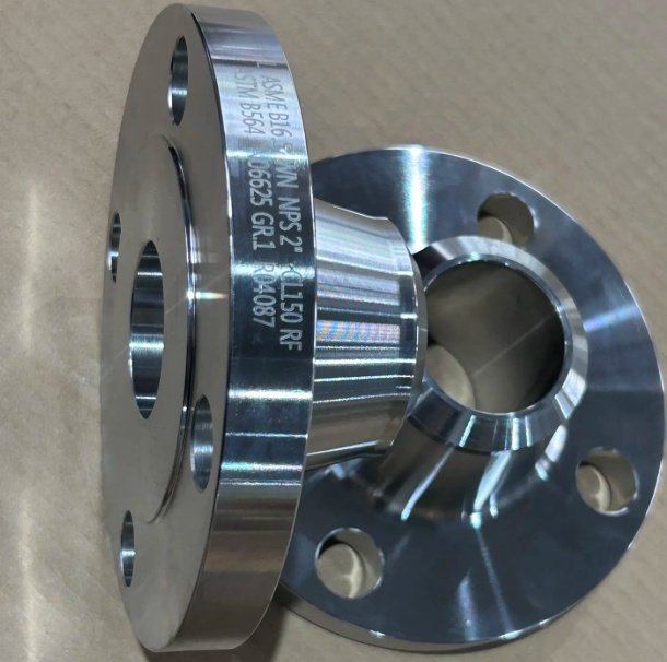
Packaging, Marking and Supply Range
Each flange can be marked with size, rating, material grade, heat number, standard and manufacturer identification as required. Marking methods include stamping, low-stress stamping, painting and labeling depending on material and project specification.
- Anti-rust protection for carbon steel flanges before shipment.
- Sealing face protection using plastic caps, plywood covers or protective films.
- Wooden cases, pallets or seaworthy packing for export transport.
- Batch separation by heat number, material grade, size and project line item.
- Custom packing marks and documentation support for EPC, distributor and end-user projects.
Available supply includes standard industrial flanges, large-diameter flanges, forged flanges, plate flanges, stainless steel flanges, carbon steel flanges, alloy steel flanges and custom machined flanges for pressure piping and equipment connections.