A motor shaft is the precision rotating component that connects an electric motor rotor to the driven mechanism, such as a gearbox, fan, pump, pulley, encoder, coupling or actuator. In practical engineering, the shaft must transmit torque while maintaining concentricity, stiffness and fatigue strength under repeated starts, stops, reversals and radial or axial loads.
This page explains motor shaft types, materials, machining methods, tolerances, surface treatments, inspection criteria and common failure modes. It is intended for engineers, sourcing teams and buyers who need to specify or evaluate standard and custom motor shafts for industrial motors, servo motors, gear motors, BLDC motors, pump motors and automation equipment.
What Is a Motor Shaft?
A motor shaft is usually a cylindrical steel or stainless steel component mounted through the rotor core or connected to the rotor assembly. It transfers mechanical power from the electromagnetic rotating system to the external load. Although it may look simple, its performance depends on fit, runout, surface finish and heat treatment, not only on diameter and length.
In a typical electric motor, the shaft interacts with bearings, rotor laminations, retaining rings, seals, couplings and load-side components. Poor shaft geometry can cause vibration, noise, bearing overheating, reduced efficiency and premature failure.
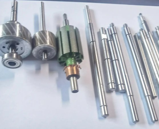
Main Types of Motor Shafts
Motor shafts can be classified by geometry, drive interface, application and manufacturing method. The correct type depends on torque transfer method, assembly requirements and operating environment.
| Motor Shaft Type | Typical Features | Common Applications |
|---|---|---|
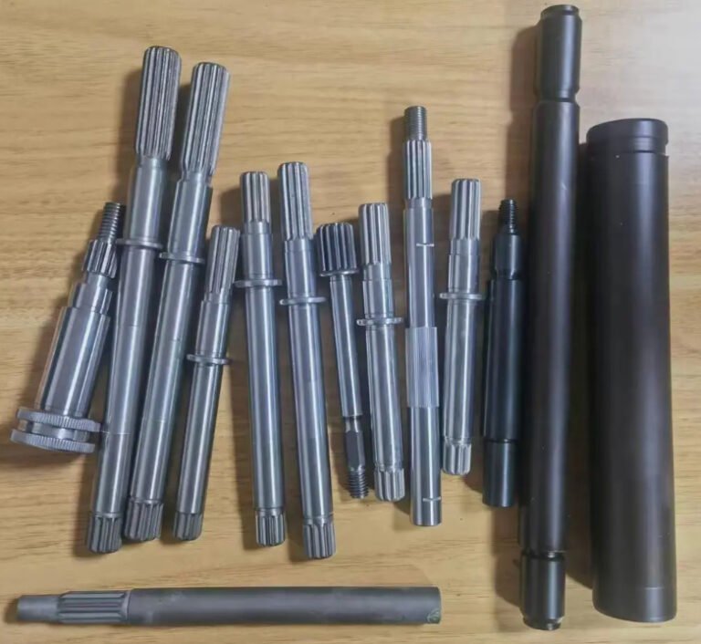
| Straight shaft | Uniform or stepped cylindrical profile | General electric motors, fans, pumps, small gear drives |
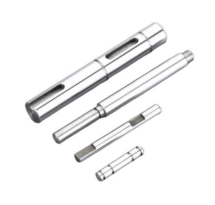
| Stepped shaft | Multiple diameters for bearings, rotor seats and couplings | Industrial motors, gear motors, servo motor assemblies |
| Keyed motor shaft | Keyway machined for torque transmission | Pulleys, sprockets, couplings, pump impellers |
| Splined shaft | Multiple teeth for high torque and accurate angular positioning | Automotive motors, robotics, hydraulic drives |
| Threaded shaft | External or internal thread for fastening or axial retention | Appliance motors, actuators, compact gear units |
| Hollow motor shaft | Central bore for weight reduction or cable routing | Servo systems, robotics, torque motors, encoders |
| Integrated rotor shaft | Shaft designed as part of the rotor assembly | BLDC motors, traction motors, high-speed motors |
Common Motor Shaft Materials
Material selection affects torsional strength, machinability, corrosion resistance, magnetic behavior, weldability and cost. For many industrial motor shafts, medium-carbon alloy steels such as 42CrMo4 / AISI 4140 are used because they provide a good balance of toughness, fatigue resistance and heat-treatment response.
| Material | Advantages | Typical Use |
|---|---|---|
| C45 / AISI 1045 carbon steel | Good machinability, economical, suitable for induction hardening | Standard motor shafts, moderate torque applications |
| 40Cr / AISI 5140 alloy steel | Higher hardenability than plain carbon steel | Gear motors, shafts requiring improved wear resistance |
| 42CrMo4 / AISI 4140 alloy steel | High strength, good fatigue performance, reliable after quench and temper | Heavy-duty motor shafts, servo shafts, industrial drives |
| 20CrMnTi carburizing steel | Hard wear-resistant surface with tough core after carburizing | Motor shafts with gears, splines or high-contact wear zones |
| 304 stainless steel | Good corrosion resistance, non-hardenable by heat treatment | Food equipment, light-duty wet environments |
| 420 stainless steel | Heat-treatable stainless steel with better hardness | Corrosive environments requiring wear resistance |
| 17-4PH stainless steel | High strength and corrosion resistance after precipitation hardening | Medical devices, aerospace-grade electromechanical systems |
Key Design Parameters for a Motor Shaft
A motor shaft drawing should define all functional surfaces clearly. Missing shaft tolerances often lead to assembly variation, bearing noise or inconsistent coupling alignment.
- Shaft diameter: Determines torque capacity, bearing fit and stiffness.
- Overall length: Controls motor envelope and coupling position.
- Bearing journals: Usually require tighter tolerances and fine surface finish.
- Rotor seat: May require interference fit, adhesive bonding or shrink fitting.
- Runout: Critical for vibration, balance and seal life.
- Shoulder geometry: Affects bearing seating and axial location.
- Keyway, spline or flat: Transfers torque to the driven component.
- Threaded ends: Used for nuts, impellers, encoders or retainers.
- Surface hardness: Important for wear, fretting and seal contact.
- Dynamic balance grade: Important for high-speed rotors and quiet motors.
Recommended Tolerances and Surface Finish
Motor shaft tolerances depend on application, shaft diameter, speed and assembly method. For bearing seats and coupling journals, total indicated runout (TIR) is often more important than a broad dimensional tolerance.
| Feature | Common Engineering Range | Why It Matters |
|---|---|---|
| Bearing journal diameter | Often h6, j6, k6 or m6 depending on bearing fit | Controls bearing inner-ring retention and operating clearance |
| Bearing journal surface roughness | Ra 0.2-0.8 μm typical | Improves bearing fit stability and reduces fretting |
| Seal contact surface | Ra 0.2-0.6 μm typical | Reduces leakage and seal wear |
| Runout at bearing seats | 0.005-0.02 mm typical for precision motors | Reduces vibration and bearing load variation |
| Keyway position | Defined by width, depth and angular location | Prevents backlash, coupling eccentricity and torque loss |
| Shoulder perpendicularity | Often 0.01-0.03 mm relative to shaft axis | Ensures bearing rings seat evenly |
The values above are general engineering references. Final tolerances should be verified against motor speed, bearing type, torque, temperature, production volume and applicable standards such as ISO fits and tolerances.
Motor Shaft Manufacturing Process
The manufacturing route for a motor shaft is selected according to material, tolerance level, hardness, batch size and feature complexity. A common process for precision shafts includes cutting, turning, heat treatment, straightening, grinding and final inspection.
- Raw material preparation: Steel bar, forged blank or stainless bar is cut to length.
- Rough turning: CNC lathe removes excess material and creates primary steps.
- Center drilling: Centers are prepared for grinding, turning between centers or inspection.
- Heat treatment: Quenching and tempering, induction hardening, carburizing or nitriding may be applied.
- Straightening: Shaft straightness is corrected after heat treatment when required.
- Finish turning: Threads, grooves, shoulders and undercuts are completed.
- Keyway or spline machining: Milling, broaching, shaping, hobbing or rolling can be used.
- Cylindrical grinding: Bearing seats and precision journals are ground to final size.
- Surface treatment: Black oxide, phosphating, plating, passivation or anti-rust oil may be applied.
- Inspection and packaging: Dimensions, runout, hardness and surface quality are checked before shipment.
When is grinding necessary for a motor shaft?
Grinding is commonly required when the bearing journal needs tight tolerance, low runout or a fine surface finish. For example, a CNC-turned shaft may hold a general diameter tolerance, but a ground bearing seat can more reliably achieve Ra 0.2-0.4 μm and micron-level roundness in precision motor applications.
Heat Treatment and Surface Treatment Options
Heat treatment improves strength, hardness and fatigue resistance. Surface treatment improves wear resistance or corrosion protection. The best combination depends on the load case and environment.
| Treatment | Typical Result | Suitable Shaft Features |
|---|---|---|
| Quench and temper | Improves core strength and toughness | Heavy-duty motor shafts and high-torque shafts |
| Induction hardening | Localized hard surface with tough core | Bearing journals, seal areas, wear zones |
| Carburizing | Hard case with ductile core | Splines, gear-integrated shafts, high-contact surfaces |
| Nitriding | High surface hardness with low distortion | Precision shafts requiring dimensional stability |
| Black oxide | Light corrosion resistance and improved appearance | General industrial motor shafts |
| Hard chrome plating | Wear and corrosion resistance | Seal contact surfaces and harsh-duty shafts |
| Passivation | Enhances stainless steel corrosion resistance | Stainless motor shafts in wet or clean environments |
Engineering Calculation Factors
A motor shaft must be checked for torsional stress, bending stress, fatigue, deflection and critical speed. For many failures, torque capacity alone is not enough; combined bending and torsion are more representative of real service conditions.
For a solid circular shaft under torque, the basic torsional shear stress is:
τ = 16T / πd³
Where τ is shear stress, T is torque and d is shaft diameter. Because stress increases rapidly as diameter decreases, a small reduction in shaft diameter can significantly reduce torque capacity. For example, reducing diameter from 20 mm to 18 mm lowers the polar section strength by roughly 27% because torsional capacity is proportional to diameter cubed.
For high-speed motors, shaft critical speed should also be reviewed. A long unsupported shaft with a heavy coupling can approach a bending resonance, causing noise, vibration and bearing overload even when the torque rating appears acceptable.
Example: why a coupling overhang can damage a motor shaft
If a pulley or coupling is mounted far from the bearing, the radial load creates a bending moment at the bearing journal and shoulder. In one typical industrial motor case, moving a belt pulley 25 mm closer to the bearing reduced calculated bending moment by about 30%, helping reduce bearing temperature and vibration amplitude.
Common Motor Shaft Failures and Root Causes
Motor shaft failures usually occur from a combination of design, manufacturing, assembly and operating factors. A visible broken shaft may be the final result of earlier misalignment, bearing looseness or stress concentration.
| Failure Symptom | Likely Cause | Engineering Countermeasure |
|---|---|---|
| Shaft breaks near shoulder | Sharp fillet, high bending moment, stress concentration | Increase fillet radius, improve surface finish, check load position |
| Bearing seat wear or fretting | Loose fit, micro-movement, poor hardness | Correct fit class, improve hardness, apply retaining compound if suitable |
| Excessive vibration | High runout, unbalance, misalignment | Improve grinding accuracy, balance rotor, inspect coupling alignment |
| Keyway cracking | High cyclic torque, sharp keyway corners | Use proper keyway radius, consider spline or larger shaft diameter |
| Corrosion pitting | Moisture, chemical exposure, inadequate coating | Select stainless steel, plating, passivation or sealed design |
| Thread stripping | Insufficient engagement, overload, soft material | Increase thread length, improve heat treatment, use correct fastener torque |
In fatigue-related failures, fracture often starts at a notch such as a keyway end, shoulder fillet, thread root or grinding mark. Reducing stress concentration is often more effective than simply changing to a stronger steel. In real motor assemblies, fatigue failure usually begins at the weakest geometric transition, not at the largest shaft diameter.
Quality Inspection for Motor Shafts
For production motor shafts, quality control should include dimensional measurement, geometric inspection, material verification and functional checks. Buyers should not rely only on outside diameter values if the shaft has bearing seats, keyways, splines or high-speed requirements.
- Material certificate: Confirms steel grade, heat number and chemical composition.
- Hardness report: Verifies quench and temper, induction hardening or carburizing results.
- Runout inspection: Measures shaft concentricity between datum surfaces.
- Roundness and cylindricity: Important for bearing and seal contact zones.
- Surface roughness test: Confirms Ra value on journals and sealing areas.
- Keyway gauge inspection: Checks width, depth, parallelism and location.
- Thread gauge inspection: Confirms external or internal thread compliance.
- Magnetic particle inspection: Detects surface cracks after heat treatment or grinding.
- Dynamic balancing: Required for rotor assemblies or high-speed applications.
For high-volume supply, process capability data such as Cpk can be used for critical dimensions. A Cpk value above 1.33 is commonly requested for stable production features, while safety-critical or automotive programs may require higher capability targets.
Buyer and Engineer Checklist Before Ordering
A clear motor shaft specification reduces quotation errors, machining rework and assembly risk. The following information is typically required for a reliable technical and commercial evaluation:
- 2D drawing with tolerances, datums and surface finish symbols
- 3D model for complex stepped shafts, splines or integrated rotor shafts
- Material grade and applicable equivalent standard
- Heat treatment requirement and target hardness range
- Critical dimensions such as bearing seats, rotor fit and coupling interface
- Runout, concentricity, perpendicularity and straightness requirements
- Keyway, spline, flat, thread or groove specifications
- Surface treatment, rust prevention and packaging requirements
- Operating speed, torque, radial load and axial load if design support is needed
- Annual volume, batch size, inspection level and documentation requirements
Documents often requested for industrial motor shaft procurement
Common documents include material test reports, dimensional inspection reports, hardness reports, surface roughness records, heat treatment certificates and coating certificates. Automotive and appliance programs may also request control plans, process flow charts, FMEA documents and PPAP documentation for production approval.
Standard Motor Shaft vs Custom Motor Shaft
Standard motor shafts are suitable when the motor and driven component follow common frame sizes and interface dimensions. Custom motor shafts are preferred when the application requires special length, unusual coupling geometry, corrosion resistance, high speed, low noise, integrated gears, hollow design or tight runout.
| Comparison Item | Standard Motor Shaft | Custom Motor Shaft |
|---|---|---|
| Lead time | Usually shorter if stock exists | Depends on tooling, machining and inspection needs |
| Cost | Lower for common sizes | Higher at low volume but optimized for function |
| Design flexibility | Limited to existing dimensions | Can match torque, bearing, rotor and coupling requirements |
| Performance optimization | Moderate | High, especially for noise, vibration and fatigue control |
| Best use case | Replacement parts and general motors | OEM motors, servo drives, pumps, robotics and special equipment |
Applications of Motor Shafts
Motor shafts are used across almost every electromechanical system where rotational power is required. Application conditions vary widely, so shaft design should be matched to duty cycle, speed, torque and environment.
- AC induction motors for industrial machinery
- DC motors for automation and motion control
- BLDC motors for fans, pumps and electric vehicles
- Servo motors for robotics, CNC machines and packaging equipment
- Gear motors for conveyors, actuators and material handling systems
- Pump motors for water treatment, chemical processing and HVAC systems
- Compressor motors and blower motors
- Home appliance motors for washing machines and kitchen equipment
- Medical and laboratory equipment motors
- Automotive and e-mobility drive components
How to Improve Motor Shaft Reliability
Reliable motor shaft performance comes from coordinated design, manufacturing and assembly control. The following practices are commonly used in professional motor engineering:
- Use generous fillet radii where shaft diameter changes.
- Avoid placing keyway ends at maximum bending stress locations.
- Specify bearing fits according to load direction and thermal expansion.
- Control runout between bearing journals and output interface.
- Choose heat treatment based on both core strength and surface wear.
- Grind bearing seats after heat treatment when precision is required.
- Balance rotor assemblies for high-speed or low-noise applications.
- Protect shafts from corrosion during storage and transport.
- Validate new shaft designs with load testing or fatigue analysis when operating conditions are severe.
A well-designed motor shaft is not only a machined steel part. It is a functional rotating component that influences torque transmission, vibration, bearing life, assembly accuracy and long-term motor reliability.