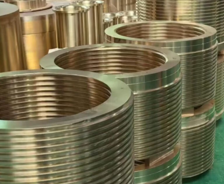
A transmission shaft is a rotating mechanical component used to transfer torque and rotational motion between a power source and a driven machine. It is found in gearboxes, drivetrains, industrial machinery, pumps, conveyors, agricultural equipment, marine systems and many other power transmission assemblies.
For engineers and buyers, selecting the correct shaft is not only a matter of diameter and length. A reliable transmission shaft must balance torque capacity, torsional stiffness, fatigue strength, alignment accuracy, surface finish, material grade, heat treatment, machining tolerance and inspection control.
What Is a Transmission Shaft?
A transmission shaft transmits mechanical power by rotating around its longitudinal axis. Depending on the application, it may carry gears, pulleys, sprockets, couplings, universal joints, bearings, seals, splines or keyed hubs. In a drivetrain, the shaft transfers torque from the engine or motor to another rotating element. In industrial machinery, it may connect a gearbox output to a driven roller, impeller, screw, spindle or actuator.
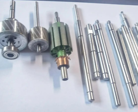
The term transmission shaft is often used together with related names such as drive shaft, gearbox shaft, propeller shaft, line shaft, jackshaft, PTO shaft, input shaft, output shaft, intermediate shaft, spline shaft and coupling shaft. Although these parts share the same core function, their geometry, load case and manufacturing process can be very different.
Common Types of Transmission Shafts
Transmission shafts can be classified by function, geometry, connection method and operating environment. The table below summarizes common shaft types and typical engineering considerations.
| Type | Typical Use | Key Engineering Considerations |
|---|---|---|
| Drive Shaft | Automotive, machinery, drivetrain systems | Torque, dynamic balance, universal joint angle, torsional vibration |
| Gearbox Input Shaft | Receives power from motor or engine | Bearing fit, spline or keyway strength, seal journal finish |
| Gearbox Output Shaft | Delivers reduced or increased speed to load | Bending load, torque peak, gear seat concentricity, fatigue resistance |
| Spline Shaft | Sliding or fixed torque transmission | Spline profile accuracy, flank contact, wear resistance, lubrication |
| Hollow Shaft | Weight-sensitive or cable-through applications | Torsional stiffness, wall thickness, critical speed, stress concentration |
| Line Shaft | Long-distance power transmission in industrial equipment | Straightness, support spacing, coupling alignment, whirling speed |
| PTO Shaft | Agricultural and mobile machinery | Telescopic movement, guard compatibility, shock load, spline wear |
| Propeller Shaft | Vehicle and marine propulsion | Balance grade, corrosion protection, angular misalignment, vibration |
Key Design Parameters for a Transmission Shaft
Correct shaft design starts with the load case. A shaft may fail even when average torque is low if shock loading, bending moment, stress concentration or poor alignment is ignored.
- Nominal torque: continuous torque transmitted during normal operation.
- Peak torque: short-duration torque caused by startup, braking, jamming or impact load.
- Rotational speed: shaft rpm, critical speed margin and balancing requirement.
- Bending load: radial forces from gears, belts, chains, impellers or overhung loads.
- Axial load: thrust from helical gears, pumps, screws or clutch mechanisms.
- Support span: distance between bearings, which strongly affects deflection.
- Connection geometry: keyway, spline, taper, thread, flange, cross hole or shrink fit.
- Service environment: temperature, corrosion, dust, lubrication, washdown or abrasive particles.
As a practical engineering rule, shafts operating with reversing torque, frequent starts or impact loads require higher fatigue margin than shafts under smooth unidirectional torque. For many industrial designs, engineers use a service factor between 1.25 and 2.5, depending on duty cycle and shock severity.
Materials and Heat Treatment
Material selection affects strength, machinability, wear resistance, hardenability, dimensional stability and cost. Common materials for transmission shafts include carbon steel, alloy steel, stainless steel and, in selected lightweight applications, aluminum alloy or titanium alloy.
| Material | Typical Advantages | Typical Applications |
|---|---|---|
| C45 / AISI 1045 | Good machinability, moderate strength, economical | General industrial shafts, rollers, low to medium load drives |
| 42CrMo4 / AISI 4140 | High tensile strength, good toughness, suitable for quenching and tempering | Gearbox shafts, heavy-duty drive shafts, machinery transmission parts |
| 20MnCr5 / 8620 | Good carburizing response, hard case with tough core | Gear shafts, spline shafts, wear-loaded transmission components |
| 17-4PH Stainless Steel | Corrosion resistance with high strength after precipitation hardening | Marine, food equipment, chemical machinery, exposed shafting |
| 304 / 316 Stainless Steel | Excellent corrosion resistance, moderate mechanical strength | Washdown equipment, pumps, hygienic machinery |
Common heat treatment routes include quenching and tempering, induction hardening, carburizing, nitriding and stress relieving. For spline shafts and gear-integrated shafts, case hardening is often used to combine a wear-resistant surface with a tough core. Typical carburized case depths may range from 0.6 mm to 1.5 mm for medium-size gear shafts, while induction hardened journals may target localized hardness on bearing or seal contact areas.
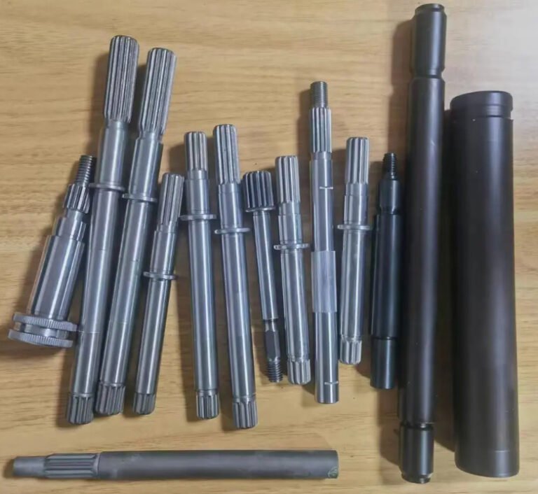
Manufacturing and Machining Process
Transmission shaft manufacturing usually combines rough forming, CNC machining, heat treatment, finishing and inspection. The process route depends on volume, material, shaft size and functional features.
- Raw material preparation: bar stock, forged blank, tube blank or near-net-shape forging is selected according to load and production volume.
- Rough turning: CNC turning removes excess material and establishes datum surfaces.
- Center drilling and support: centers are prepared for between-center turning or cylindrical grinding to improve coaxial accuracy.
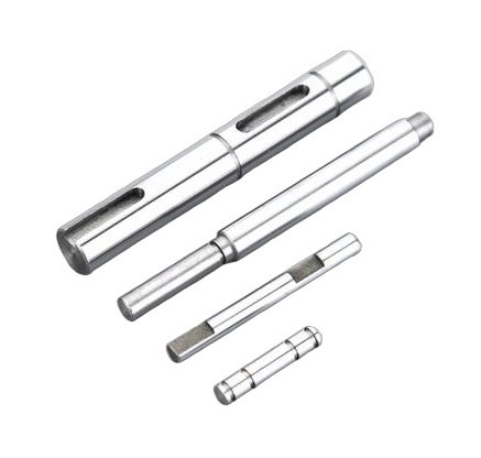
- Milling and slotting: keyways, flats, cross holes, oil grooves or retaining-ring grooves are machined.
- Spline or gear machining: external splines may be cut by hobbing, shaping, milling, broaching or rolling, depending on profile and quantity.
- Heat treatment: quenching, tempering, carburizing, induction hardening or nitriding is performed to achieve mechanical properties.
- Finish machining: grinding, hard turning, honing or polishing controls bearing seats, seal journals and critical diameters.
- Balancing and inspection: dynamic balance, runout, hardness, dimensional accuracy and surface finish are verified.
For high-speed transmission shafts, finish grinding is often necessary because small geometry errors can generate vibration, bearing heat and premature seal wear. Seal journals commonly require a fine surface finish, while bearing seats require controlled diameter tolerance and roundness.
Tolerances, Surface Finish and Balancing
Shaft tolerance should be specified according to mating components and operating speed. Overly loose fits cause fretting and vibration, while overly tight fits can create assembly damage, bearing preload errors or excessive hoop stress.
| Feature | Common Requirement | Reason |
|---|---|---|
| Bearing Seat | Often ISO h6, k6, m6 or application-specific fit | Controls bearing mounting accuracy and creep resistance |
| Seal Journal | Ra 0.2–0.8 µm is commonly used depending on seal type | Reduces leakage, friction heat and seal lip wear |
| Gear or Coupling Seat | Concentricity and runout controlled to drawing datum | Improves gear mesh, coupling alignment and torque uniformity |
| Keyway | Width, depth and corner radius controlled | Prevents backlash, hub cracking and stress concentration |
| Spline | Profile, pitch, major/minor diameter and flank fit controlled | Ensures contact area, sliding performance and torque capacity |
| Overall Straightness | Specified by length, rpm and bearing span | Limits vibration and rotating imbalance |
Dynamic balancing becomes increasingly important as speed and shaft length increase. Standards such as ISO 21940 are commonly referenced for balancing quality grades. For example, a high-speed industrial shaft may require a tighter balance grade than a slow conveyor shaft, even if both transmit similar torque.
Engineering note: why runout matters
A shaft with excessive runout can create cyclic radial loading at bearings and seals. In a gearbox, this may appear as abnormal gear mesh noise, localized tooth wear or elevated bearing temperature. In field troubleshooting, reducing gear-seat runout from about 0.08 mm to below 0.02 mm can significantly reduce vibration amplitude in many medium-speed rotating assemblies, although the exact result depends on speed, gear quality, bearing stiffness and housing accuracy.
Failure Modes and Practical Engineering Problems
Most transmission shaft failures are linked to fatigue, overload, misalignment, inadequate lubrication, poor heat treatment, machining defects or incorrect fit selection. A broken shaft is often the final symptom; the root cause may be in design, assembly or operating conditions.
- Fatigue fracture: usually starts at a keyway corner, shoulder fillet, thread root, cross hole or spline root.
- Torsional overload: caused by sudden jamming, clutch shock, braking torque or incorrect motor sizing.
- Bending failure: common with overhung pulleys, chain sprockets or unsupported long spans.
- Fretting wear: appears at loose bearing seats, coupling hubs or spline interfaces.
- Surface pitting or scoring: associated with poor lubrication, contamination or excessive contact stress.
- Thermal distortion: caused by improper heat treatment, welding repair or uneven grinding heat.
- Corrosion fatigue: common in marine, washdown, mining and chemical environments.
In one typical industrial troubleshooting case, a conveyor drive shaft experienced repeated cracking at the keyway after 4 to 6 months of operation. The root causes were a sharp keyway corner, high belt tension and frequent start-stop torque peaks. After increasing the shoulder fillet radius, changing to a tougher alloy steel, improving keyway finish and reducing belt preload, service life can often improve from months to multiple years under the same production duty. The exact improvement should be validated by load measurement and inspection data.
How to Specify a Transmission Shaft for Purchase
Buyers and engineers should provide more than a simple drawing if the shaft is safety-critical or used in continuous production equipment. A complete specification reduces quotation errors, machining rework and field failure risk.
- 2D drawing with dimensions, datum references, tolerances and surface finish symbols.
- 3D model in STEP, IGES or native CAD format for complex geometry.
- Material grade and equivalent standard, such as AISI, EN, JIS or GB.
- Heat treatment requirement, hardness range and case depth if applicable.
- Torque, speed, duty cycle, peak load and operating environment.
- Bearing, seal, gear, pulley, sprocket, coupling or spline interface details.
- Required inspection reports, such as dimensional report, hardness report or material certificate.
- Quantity, production batch size, expected annual usage and packaging requirement.
A well-defined purchase specification should identify which dimensions are functional and which are non-critical. This helps the manufacturer allocate precision where it matters, improving both performance and cost control. For example, a ground bearing seat may require tight tolerance, while a non-contact relief diameter may not need the same machining precision.
Buyer checklist before placing an order
- Confirm whether the shaft is a new design, replacement part or reverse-engineered component.
- Check whether the mating parts are metric or inch standard.
- Confirm if the shaft must be balanced after key, coupling or flange installation.
- Define whether inspection is based on 100% checking or sampling.
- Ask whether protective oil, VCI paper, caps or export packaging is needed.
Application Areas
Transmission shafts are used wherever controlled mechanical power transfer is required. The load conditions vary widely by industry, so the same nominal shaft diameter may need different materials, tolerances and surface treatments.
| Industry | Typical Shaft Applications | Important Requirements |
|---|---|---|
| Automotive and EV | Drive shafts, intermediate shafts, gearbox shafts | NVH control, balance, spline accuracy, lightweight design |
| Industrial Gearboxes | Input shafts, output shafts, pinion shafts | Fatigue strength, bearing fit, gear-seat runout, hardness control |
| Agricultural Machinery | PTO shafts, harvester shafts, spreader shafts | Shock load resistance, corrosion protection, serviceability |
| Mining and Construction | Crusher shafts, conveyor shafts, heavy-duty drive shafts | High torque, impact resistance, abrasion and dust protection |
| Marine Equipment | Propeller shafts, pump shafts, winch shafts | Corrosion resistance, straightness, seal compatibility |
| Packaging and Food Machinery | Roller shafts, timing shafts, stainless shafts | Cleanability, stainless material, accurate timing and low vibration |
Quality Control and Documentation
For production transmission shafts, quality control should match the risk level of the application. A low-speed adjustment shaft may only require basic dimensional inspection, while a high-speed gearbox shaft may require complete traceability and multiple process controls.
- Dimensional inspection: diameter, length, shoulder location, thread, groove, spline and keyway dimensions.
- Geometric inspection: runout, concentricity, cylindricity, straightness, perpendicularity and coaxiality.
- Material verification: mill certificate, chemical composition and mechanical property confirmation.
- Hardness testing: surface hardness, core hardness and case depth verification when required.
- Surface inspection: roughness measurement, magnetic particle testing, visual checks and crack detection.
- Balancing report: residual unbalance data for shafts used at higher rotational speeds.
- Process traceability: heat number, batch number, heat treatment record and inspection report.
Standards often referenced in shaft-related work include ISO 286 for limits and fits, ISO 21940 for balancing, ISO 1940 legacy balancing references, ISO 14 and DIN 5480 for spline-related designs, and relevant AGMA or DIN standards for gear shafts. The applicable standard should always be confirmed by the drawing and end-use requirement.
Specification example for a machined transmission shaft
Material: 42CrMo4 / AISI 4140. Heat treatment: quenched and tempered to 28–34 HRC. Bearing seats: ground to specified ISO fit. Seal journal: Ra 0.4 µm. Gear seat runout: controlled to drawing datum. Keyway: milled with controlled corner radius. Inspection: material certificate, hardness report, dimensional report and runout record. Packaging: rust preventive oil and individual protection for machined surfaces.
Transmission Shaft Selection Summary
A high-quality transmission shaft is the result of correct design assumptions, suitable material, controlled heat treatment, precision machining and reliable inspection. When comparing suppliers or preparing a drawing, focus on the functional requirements: transmitted torque, speed, bearing arrangement, fit tolerance, shaft deflection, connection method, surface hardness and operating environment.
For critical applications, the lowest unit price is rarely the lowest lifecycle cost. Better control of geometry, surface finish, heat treatment and balancing can reduce downtime, bearing failure, vibration and replacement frequency. A properly specified transmission shaft improves power transmission efficiency, equipment reliability and long-term maintenance predictability.