
Metal prototype manufacturing helps engineering, procurement, and product teams verify form, fit, function, manufacturability, and risk before investing in production tooling. This guide explains how to choose metal prototyping services, compare processes, specify requirements, and avoid common cost and quality problems.
Whether the search intent is rapid metal prototyping for a new product launch, metal part prototyping for a fixture, or low-volume metal parts for validation testing, the core decision is the same: select the process, material, tolerance, and inspection plan that match the prototype’s real purpose.
What Is Metal Prototype Manufacturing?
Metal prototype manufacturing is the production of one-off or low-volume metal components before full-scale manufacturing. A metal prototype may be used for mechanical testing, dimensional verification, thermal testing, visual review, assembly trials, regulatory validation, or investor demonstration.
Unlike plastic prototypes, metal prototypes often need to withstand load, heat, vibration, corrosion, wear, pressure, or electrical conductivity requirements. This makes process selection more important. For example, a decorative aluminum enclosure and a load-bearing 17-4 PH stainless steel bracket may both be prototypes, but they require very different manufacturing and inspection strategies.
In search and sourcing language, terms such as metal rapid prototyping, rapid prototyping, metal prototyping, metal parts rapid prototyping, and metal part prototyping often overlap. In engineering practice, each term should be tied to a defined technical objective: speed, accuracy, strength, surface finish, or production readiness.
When to Use Rapid Metal Prototyping
Rapid metal prototyping is most valuable when design uncertainty is high and the cost of late-stage design changes is significant. It is commonly used in robotics, aerospace, medical devices, automotive, energy equipment, electronics, industrial automation, and consumer hardware.
Best-Fit Use Cases
- Testing mechanical strength, stiffness, and fatigue behavior before production release.
- Checking assembly interfaces, fastener access, gasket compression, and mating surfaces.
- Validating thermal paths in heat sinks, housings, battery trays, and power electronics parts.
- Producing bridge parts while production tooling, casting dies, or stamping tools are being built.
- Comparing materials such as aluminum, stainless steel, titanium, copper, brass, and tool steel.
- Preparing functional samples for regulatory, customer, or internal engineering review.
A useful rule: use rapid prototyping when the design is still changing, and use production-intent prototyping when the design must prove it can be manufactured repeatedly at the required cost and quality.
Engineering note: speed is not the only definition of “rapid”
A prototype delivered in three days is not always better than one delivered in ten days. If the fast option uses the wrong alloy, skips heat treatment, or ignores critical tolerances, the test result may be misleading. In professional metal prototyping services, “rapid” should mean the shortest reliable path to a decision.
Core Metal Prototyping Processes
The best process depends on geometry, quantity, strength, tolerance, surface finish, material, and budget. Most suppliers offering metal prototyping services combine several manufacturing methods rather than relying on only one.
| Process | Best For | Typical Strength Profile | Typical Prototype Lead Time | Key Limitations |
|---|---|---|---|---|
| CNC Machining | Accurate functional metal parts, housings, brackets, shafts, fixtures | Excellent; uses wrought bar, plate, or billet material | 3 to 15 business days depending on complexity | Cost rises with deep cavities, tight radii, complex setups, and high material removal |
| Sheet Metal Fabrication | Enclosures, panels, clips, covers, shields, chassis, brackets | Excellent for formed sheet structures | 3 to 12 business days | Bend radius, tooling access, flange length, and grain direction must be considered |
| Metal 3D Printing | Complex internal channels, lightweight lattices, organic shapes, aerospace and medical prototypes | Good to excellent after proper heat treatment and process control | 5 to 20 business days | Surface roughness, anisotropy, support removal, and qualification cost |
| Wire EDM | High-precision profiles, hardened steels, slots, gears, punches, dies | Excellent; minimal cutting forces | 4 to 15 business days | Only conductive materials; slower for thick sections |
| Laser Cutting | Flat metal blanks, panels, gaskets, brackets, quick sheet prototypes | Good; depends on sheet material | 1 to 7 business days | Heat-affected edge, kerf width, and limited 3D geometry |
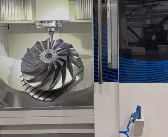
| Investment Casting or Sand Casting | Production-like cast prototypes, pump housings, impellers, complex metal shapes | Comparable to cast production parts when controlled | 2 to 8 weeks | Longer lead time, shrinkage compensation, porosity risk, tooling or pattern cost |
CNC Machining for Metal Prototypes
CNC machining is often the first choice for functional metal prototypes because it produces accurate parts from real engineering alloys. It is suitable for aluminum 6061-T6, aluminum 7075-T6, stainless steel 304 and 316, 17-4 PH, mild steel, tool steel, brass, bronze, copper, magnesium, and titanium.
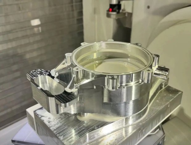
CNC is especially effective when the prototype must represent production-machined components. For example, a machined aluminum gearbox cover can verify bearing fits, bolt-hole locations, sealing surfaces, and thermal behavior before die-casting or production machining begins.
Sheet Metal Prototyping
Sheet metal prototyping is widely used for enclosures, EV battery components, electrical cabinets, medical device housings, computer chassis, and industrial brackets. It combines laser cutting, punching, bending, welding, riveting, PEM hardware insertion, grinding, and finishing.
Designers should confirm bend radius, K-factor, bend allowance, minimum flange length, hole-to-bend distance, and fastener clearance before releasing drawings. Small changes in bend geometry can reduce scrap and improve repeatability.
Metal 3D Printing
Metal additive manufacturing processes such as DMLS, SLM, LPBF, binder jetting, and directed energy deposition are useful for geometries that cannot be machined easily. Examples include conformal cooling channels, topology-optimized brackets, porous medical structures, and integrated manifolds.
However, metal 3D printing is not automatically cheaper or faster for every prototype. Support structures, heat treatment, stress relief, HIP processing, machining of critical faces, and inspection can add significant time and cost.
Process selection example
A robotics team needed a lightweight arm bracket for load testing. The first concept had internal ribs and curved topology-optimized geometry, making metal 3D printing attractive. After testing, the team simplified the design into a three-axis CNC-machined aluminum 7075-T6 bracket. The machined version reduced unit cost by about 42% at a 20-piece pilot quantity while keeping stiffness within the design target.
Material Selection for Metal Parts
Material choice affects strength, machinability, corrosion resistance, finishing, weight, conductivity, heat resistance, and cost. For accurate testing, prototype material should match the final production material whenever possible.
| Material | Common Grades | Why Engineers Choose It | Prototype Considerations |
|---|---|---|---|
| Aluminum | 6061-T6, 7075-T6, 5052, 2024 | Lightweight, machinable, corrosion resistant, easy to anodize | 6061 is versatile; 7075 provides higher strength but lower corrosion resistance |
| Stainless Steel | 304, 316, 17-4 PH, 420 | Corrosion resistance, strength, medical and food equipment compatibility | More expensive to machine than aluminum; work hardening must be controlled |
| Carbon Steel | 1018, 1045, A36, 4140 | Strong, economical, weldable, widely available | May require plating, painting, black oxide, or oiling to prevent corrosion |
| Titanium | Grade 2, Grade 5 Ti-6Al-4V | High strength-to-weight ratio, corrosion resistance, biocompatibility | Higher machining cost; heat control and tooling strategy are critical |
| Copper and Brass | C110, C101, C360 | Electrical conductivity, thermal conductivity, corrosion resistance, appearance | Pure copper can be gummy in machining; brass is easier but less conductive |
| Tool Steel | D2, A2, O1, H13, P20 | Wear resistance, hardness, mold and die applications | Heat treatment can change dimensions; finish machining after hardening may be required |
For buyers sourcing metal parts, it is not enough to specify “stainless steel” or “aluminum.” The grade, temper, hardness, heat treatment condition, and certification requirements should be defined. A prototype made from aluminum 6061-O will not behave like aluminum 6061-T6 under load.
Design Rules That Reduce Cost and Lead Time
Good prototype design does not mean removing every advanced feature. It means understanding which features are critical and which features create unnecessary machining time, tool wear, scrap, or inspection complexity.
Rules for CNC Metal Part Prototyping
- Use standard hole sizes and thread specifications when possible.
- Avoid deep narrow pockets unless they are functionally required.
- Increase internal corner radii to match available end mills.
- Allow access for cutting tools, deburring tools, and inspection probes.
- Specify tight tolerances only on functional interfaces.
- Use datum structures that match real assembly requirements.
Rules for Sheet Metal Prototyping
- Keep holes away from bend lines to reduce distortion.
- Use consistent bend radii across the design where possible.
- Check whether the selected sheet thickness is locally available.
- Confirm welding distortion risk on thin stainless or aluminum sheets.
- Use tabs, slots, and self-locating geometry to improve assembly accuracy.
Rules for Metal Additive Manufacturing
- Design for build orientation, support removal, and powder evacuation.
- Machine critical mounting surfaces after printing.
- Account for anisotropic mechanical behavior when testing load-bearing parts.
- Use lattice structures only where inspection and cleaning are feasible.
- Define post-processing steps such as stress relief, HIP, shot peening, and polishing.
A common error in metal parts rapid prototyping is applying production tolerances too early. If a prototype is intended only to check ergonomic fit or packaging space, looser tolerances can reduce cost and speed up delivery. If the prototype is intended for fatigue testing or sealing performance, tight tolerances and material traceability may be essential.
Tolerances, Inspection, and Validation
Tolerance strategy separates useful prototypes from misleading prototypes. A drawing with every dimension marked ±0.01 mm may look precise, but it can increase cost without improving engineering confidence.
| Feature Type | Typical Prototype Control | Recommended Inspection Method |
|---|---|---|
| Bearing bore | Tight size, roundness, surface finish | Bore gauge, CMM, surface roughness tester |
| Threaded hole | Thread depth, pitch, perpendicularity | Go/no-go gauge, pin gauge, visual inspection |
| Sealing face | Flatness, surface roughness, scratches | CMM, optical flat, profilometer |
| Sheet metal bend | Bend angle, flange length, hole position | Height gauge, CMM, fixture check |
| Printed internal channel | Blockage, porosity, wall thickness | CT scanning, pressure test, flow test |
Professional suppliers may provide first article inspection, CMM reports, material certificates, hardness test results, coating thickness reports, RoHS/REACH documentation, pressure testing, leak testing, or non-destructive testing. The inspection plan should match the risk of the part.
Practical tolerance benchmark
Many CNC prototype shops can hold general tolerances around ±0.05 mm to ±0.13 mm on common machined features, depending on geometry, material, machine setup, and inspection method. Tolerances tighter than ±0.025 mm are possible in many cases, but they should be applied selectively to functional features because they often require additional setups, slower machining, controlled temperature, and more inspection time.
Surface Finishing for Metal Prototypes
Surface finish can change appearance, corrosion resistance, conductivity, friction, wear, fatigue behavior, and assembly performance. A cosmetic prototype may need a different finish than a test prototype.
Common Metal Prototype Finishes
- As-machined finish for fast functional verification.
- Bead blasting for uniform matte texture.
- Anodizing for aluminum corrosion resistance and appearance.
- Hardcoat anodizing for wear resistance on aluminum parts.
- Passivation for stainless steel corrosion resistance.
- Black oxide for mild corrosion protection and reduced glare on steel.
- Electroless nickel plating for wear resistance and uniform coating thickness.
- Powder coating and wet painting for appearance and environmental protection.
- Polishing for medical, food, optical, or decorative applications.
Finishing should be included in the design review. For example, anodizing can slightly affect dimensions, polishing can round edges, and plating can build up on threads or tight bores. Critical features may need masking or post-finish machining.
Cost Drivers and Typical Lead Times
The cost of a metal prototype is driven by engineering complexity, not only size. A small titanium part with five-axis machining, tight tolerances, and inspection reporting can cost more than a large aluminum plate with simple holes.
Major Cost Drivers
- Material grade, stock size, availability, and certification requirements.
- Number of machine setups and required workholding.
- Deep pockets, thin walls, micro features, and difficult tool access.
- Tight tolerances, GD&T requirements, and surface finish callouts.
- Heat treatment, stress relief, coating, plating, and special finishing.
- Inspection reports, traceability, regulatory documentation, and packaging requirements.
- Quantity: one piece may carry most programming and setup cost; 10 to 50 pieces can reduce unit cost significantly.
| Prototype Scenario | Likely Process | Typical Lead Time | Cost Sensitivity |
|---|---|---|---|
| Simple aluminum bracket, 1 to 5 pieces | CNC machining or sheet metal | 3 to 7 business days | Moderate |
| Stainless steel medical housing with finish | CNC machining plus passivation or polishing | 7 to 18 business days | High |
| Complex titanium lattice component | Metal 3D printing plus heat treatment | 10 to 25 business days | High |
| Laser-cut sheet metal enclosure | Laser cutting, bending, hardware insertion | 4 to 12 business days | Moderate |
| Production-like cast housing | Prototype casting and machining | 3 to 8 weeks | High initially, lower if design stabilizes |
In procurement terms, the lowest unit price is not always the lowest project cost. If a supplier ships parts without deburring, misses a datum scheme, or substitutes material, engineering time and schedule delays can exceed the initial savings.
How Buyers Should Specify Metal Prototype Requirements
Clear input data reduces quoting time, prevents rework, and improves the quality of technical feedback. Buyers should provide both design files and manufacturing intent.
Recommended RFQ Package
- 3D CAD file in STEP, Parasolid, or native format.
- 2D drawing in PDF with critical dimensions, tolerances, datums, threads, and finishes.
- Material grade, temper, hardness, and any approved substitutes.
- Quantity for prototype stage and expected pilot or production quantity.
- Required process if fixed, or permission for supplier process recommendations.
- Surface finish, coating, color, masking, and cosmetic acceptance criteria.
- Inspection requirements such as CMM report, first article inspection, or material certificate.
- Functional purpose of the part: cosmetic review, assembly test, load test, pressure test, thermal test, or production validation.
- Delivery requirement and any packaging, labeling, or export documentation needs.
From an engineer’s perspective, sharing the function of the prototype is often more useful than only sending geometry. If a supplier knows that a sealing surface is critical while the external contour is cosmetic, they can focus process control where it matters most.
Buyer-side risk checklist
Before approving a quote, confirm whether the price includes material certification, deburring, finishing, inspection, packaging, taxes, and shipping. Also verify whether lead time begins at quote approval, payment, final drawing release, or material arrival. These details are frequent causes of prototype schedule surprises.
Common Failure Modes and How to Prevent Them
Metal prototypes can fail for design, manufacturing, inspection, or communication reasons. The most expensive failures are often discovered late, after assembly or testing has started.
| Failure Mode | Likely Cause | Prevention Method |
|---|---|---|
| Part does not assemble | Incorrect datum scheme, tolerance stack-up, missed interference | Use assembly-level tolerance analysis and inspect functional datums |
| Threads strip or fasteners loosen | Wrong thread depth, soft material, no insert, poor torque specification | Define thread engagement, inserts, torque limits, and material condition |
| Prototype cracks during bending | Incorrect bend radius, wrong grain direction, unsuitable alloy temper | Check bend tables and material formability before fabrication |
| Printed metal part warps | Residual stress, poor orientation, insufficient heat treatment | Plan build orientation, stress relief, supports, and post-machining |
| Leak test fails | Porosity, poor weld, surface scratches, flatness issue | Use pressure testing, weld qualification, sealing-face inspection, and correct finish |
| Finish does not match expectation | No cosmetic standard, inconsistent blasting, coating buildup | Define finish sample, color standard, masking areas, and acceptable defects |
A practical approach is to classify prototype features as critical, important, or non-critical. Critical features receive tighter tolerances and inspection; non-critical features are controlled by general tolerances. This prevents over-engineering while protecting test validity.
Prototype-to-Production Transition
A successful metal prototype is not only a part that works once. It should generate evidence for the next decision: design revision, pilot run, tooling investment, supplier qualification, or production launch.
Questions to Answer Before Production
- Did the prototype use the same material and heat treatment planned for production?
- Were any features hand-finished, manually adjusted, or reworked?
- Are tolerances realistic for production volume and cost targets?
- Can inspection be scaled without excessive cycle time?
- Does the design require casting, forging, stamping, extrusion, machining, additive manufacturing, or a hybrid process?
- Are there supply chain risks for material, coating, special tooling, or certification?
- Does the prototype reveal opportunities to consolidate parts, reduce fasteners, or simplify assembly?
The best production transition happens when the prototype supplier, design engineer, manufacturing engineer, and buyer align on what must remain unchanged and what can be optimized. A metal prototype should capture lessons about geometry, material behavior, assembly method, finish, inspection, and cost structure.
Conclusion
Metal prototype manufacturing is a technical decision-making tool, not just a fast way to make parts. Choosing the right combination of CNC machining, sheet metal fabrication, metal 3D printing, casting, EDM, finishing, and inspection can shorten development cycles while improving confidence in performance.
For accurate results, define the purpose of each prototype, select materials carefully, apply tolerances only where needed, and provide complete RFQ data. When rapid prototyping is matched with sound engineering judgment, metal prototypes become a reliable bridge between CAD design and production-ready metal parts.