
Impeller Machining Services
Impeller machining is the precision manufacturing process used to produce rotating flow components for pumps, compressors, blowers, turbines, mixers and fluid handling equipment. A well-machined impeller directly affects hydraulic efficiency, pressure ratio, vibration, cavitation resistance, service life and energy consumption. For buyers and engineers, the challenge is not only finding a CNC supplier, but selecting a manufacturing partner that understands blade geometry, material behavior, balancing requirements and inspection documentation.
- Fast prototype & low MOQ support
- Tight tolerance up to +0.002mm
- Surface finishing available
- Engineering review before production
Impeller Types Used in Machining Projects
Details
Impeller machining converts raw material or a preform into a finished rotating component with accurate blade profiles, hub geometry, bore size, keyways, balance features and surface finish. The process may include rough milling, semi-finishing, 5-axis blade finishing, turning, drilling, wire EDM, deburring, polishing, dynamic balancing and dimensional inspection.In high-speed rotating equipment, small deviations can create significant performance losses. A blade profile error of only a few hundredths of a millimeter may influence flow separation, while an uneven mass distribution can increase bearing load and vibration. This is why impeller machining requires both CNC capability and application-specific process planning. The keyword Impeller types is often searched by engineers who need to compare designs before requesting machining, repair or reverse engineering. Each impeller type has different machining difficulty, inspection requirements and cost drivers.Open impeller
Common Applications
Slurry pumps, wastewater pumps, mixersMachining Considerations
Easier tool access, but blade stiffness and edge deformation must be controlled.Semi-open impeller
Common Applications
Centrifugal pumps, chemical processing, food equipmentMachining Considerations
Requires accurate blade height, back shroud flatness and clearance control.Closed impeller
Common Applications
High-efficiency pumps, water treatment, petrochemical equipmentMachining Considerations
Internal passages can be difficult to machine and inspect; casting plus finish machining is common.Compressor impeller
Common Applications
Turbochargers, centrifugal compressors, air separation, refrigerationMachining Considerations
Complex 3D blades, thin splitter blades and tight profile tolerances often require simultaneous 5-axis milling.Common Applications
Microturbines, turbo expanders, energy recovery systems
Machining Considerations
Heat-resistant alloys, fatigue-critical geometry and stringent balance requirements are typical.
Common Applications
Fans, marine propellers, cooling systems, agitatorsMachining Considerations
Large blade surfaces require stable fixturing, controlled pitch and consistent surface finish.Blisk or integrally bladed rotor
Common Applications: Aerospace compressors, high-speed turbomachinery; Machining Considerations: One-piece rotor and blade construction; very demanding toolpath, inspection and repair strategy.Open, semi-open or closed impeller: which is easier to machine?
Open impellers usually provide better tool access and shorter machining cycles. Semi-open impellers add clearance and shroud-control requirements. Closed impellers can be the most difficult when internal flow passages are inaccessible after assembly or casting, so the manufacturing route may combine casting, CNC turning, grinding, EDM and final balancing.Materials for CNC Impeller Machining
Aluminum alloys
6061, 6082, 7075 and forged aluminum are common for compressor wheels, prototypes and lightweight applications.Stainless steels
304, 316, 316L, 17-4PH and duplex stainless steels are used where corrosion resistance and mechanical strength are required.Titanium alloys
Ti-6Al-4V is selected for high strength-to-weight ratio and corrosion resistance, but it requires heat-control machining strategies.Nickel-based alloys
Inconel 625, Inconel 718 and similar alloys are used for high-temperature and high-stress applications.Bronze and brass
Marine, pump and legacy machinery applications often use bronze alloys for corrosion and wear performance.Engineering plastics
PEEK, PVDF and reinforced polymers may be used for chemical resistance, low weight or special fluid compatibility.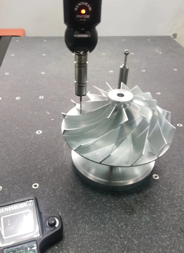
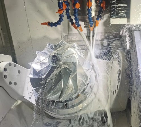
5-Axis CNC Machining Process for Impellers
A professional impeller machining workflow starts before cutting metal. The best results come from reviewing the CAD model, flow-critical surfaces, tolerance stack-up, minimum tool access, surface finish zones, balance allowance and inspection method. The most critical machining decision is often toolpath strategy. For high-efficiency compressor and pump impellers, blade profile accuracy must be maintained while avoiding chatter, rubbing, edge burning or polishing-induced geometry changes.
1
Preparation
- DFM review: Analyze blade thickness, tool accessibility, fillet radii, undercuts, datum structure and material removal volume.
- Blank preparation: Sawing, forging, casting cleanup, stress relief, turning or pre-machining the billet to a stable condition.
2
Machining
- Rough machining: Remove bulk material while leaving controlled stock for finishing. Adaptive milling helps reduce tool load.
- Semi-finishing: Establish blade shape, hub profile and shroud regions while minimizing residual stress and distortion.
More
- Finish machining: Apply simultaneous 5-axis toolpaths to achieve accurate blade surfaces and smooth flow paths.
- Deburring and polishing: Remove burrs from leading edges, trailing edges, blade roots and internal channels without changing functional geometry.
3
Quality Control
- Inspection: Use CMM, optical scanning, profile comparison, runout measurement, bore inspection and surface roughness checks.
- Balancing: Perform static or dynamic balancing according to the operating speed and applicable quality grade.
Typical Tolerances, Surface Finishes and Balancing Targets
When is dynamic balancing required?
Dynamic balancing is typically required when the impeller operates at high RPM, has a large diameter-to-width ratio, includes asymmetric features or is used in equipment sensitive to vibration. Even for smaller impellers, balancing may be specified if the assembly includes tight bearing clearance, mechanical seals or high acoustic requirements.
Geometric Accuracy
- Blade profile: ±0.02 mm to ±0.10 mm — Affects aerodynamic or hydraulic efficiency and flow stability.
- Bore diameter: H7 or drawing-specific fit — Controls shaft fit, concentricity and vibration behavior.
- Runout: 0.01 mm to 0.05 mm typical for precision rotors — Influences rotational stability and seal clearance.
Surface Quality
- Surface roughness: Ra 0.4 µm to Ra 1.6 µm for many flow surfaces — Impacts flow losses, fouling tendency and fatigue initiation.
- Blade edges and fillets — Smooth transitions reduce stress concentrations and improve fatigue life.
- Internal channels — Polishing critical flow passages minimizes turbulence, pressure drop, and corrosion initiation points.
More
- Surface treatment — Techniques such as anodizing, passivation, or coating may be applied for corrosion resistance, wear protection, or improved fluid compatibility.
- Measurement and control — Use profilometers, optical scanners, or interferometry to ensure surfaces meet tolerance; deviations can affect efficiency, vibration, and long-term durability.
Dynamic Performance
- Dynamic balance: Commonly G2.5, G1.0 or project-specific grade — Reduces vibration, bearing wear and noise.
- Many rotating components reference balancing concepts from ISO 1940 or ISO 21940. High-speed aerospace or energy applications may require more stringent internal standards, overspeed testing or documented rotor dynamics review.
Common Engineering Problems in Impeller Machining
Real impeller projects often fail for reasons that are not obvious in a quotation. The geometry may look machinable, but blade vibration, tool reach, material distortion or inspection access can create cost and delivery risks.
- Thin blade chatter: Long, flexible blades may vibrate during finishing, leaving poor surface quality or dimensional error.
- Tool collision risk: Splitter blades, deep passages and reverse-curvature surfaces require verified 5-axis simulation.
- Heat distortion: Titanium, stainless steel and nickel alloys can move after heavy material removal if stress relief is not planned.
- Leading edge damage: Aggressive deburring can change aerodynamic edges and reduce efficiency.
- Inconsistent polishing: Manual polishing may improve roughness but damage blade symmetry if not controlled.
- Unclear datum scheme: If inspection datums do not match assembly datums, a part may pass inspection but fail during installation.
A useful engineering practice is to separate surfaces into functional categories: flow-critical surfaces, assembly interfaces, balance correction zones and non-critical clearance areas. This allows the machining supplier to focus time and inspection effort where performance depends on precision.
Representative Machining Results from Realistic Projects
The following examples illustrate practical results that can be achieved when CAD quality, fixturing, toolpath strategy and inspection planning are aligned.
| Project | Material and Size | Manufacturing Challenge | Measured Outcome |
|---|---|---|---|
| Centrifugal compressor impeller | 7075-T6 aluminum, 180 mm diameter | Thin splitter blades and high-speed balance requirement | Blade profile within ±0.025 mm, Ra 0.8 µm flow surfaces, balanced to G1.0 |
| Chemical pump closed impeller | 316L stainless steel, 240 mm diameter | Corrosion-resistant material and narrow vane passages | Bore tolerance H7, runout below 0.03 mm, final passivation after machining |
| Prototype turbine wheel | Inconel 718, 95 mm diameter | Heat-resistant alloy and tight blade root radii | Controlled tool wear with staged roughing, inspected by 3D scan and CMM datum checks |
In one representative compressor impeller case, switching from indexed 3+2 finishing to simultaneous 5-axis finishing reduced manual blending time by approximately 35% and improved repeatability between blades. The main benefit was not only shorter labor time, but also more consistent blade geometry for balancing and final assembly.
Inspection and Quality Documentation
Precision impeller manufacturing should include a defined inspection plan before machining begins. For complex blades, simple caliper checks are not enough. A reliable supplier will combine contact and non-contact inspection methods depending on the geometry and tolerance level.
- CMM inspection: Measures datums, bores, runout, keyways, mounting faces and selected blade points.
- 3D scanning: Compares the full blade surface against the CAD model and visualizes deviation maps.
- Surface roughness testing: Confirms Ra or Rz values on flow surfaces where accessible.
- Dynamic balancing report: Records balance speed, quality grade, correction method and residual unbalance.
- Material traceability: Confirms alloy grade, heat number, heat treatment and compliance documents.
- NDT when required: Dye penetrant, ultrasonic or radiographic testing may be specified for safety-critical parts.
For high-value parts, inspection traceability should connect the drawing revision, CAD model version, material batch, process route, operator records and final acceptance report. This is especially important for aerospace, energy, petrochemical and medical fluid equipment applications.
Is 3D scanning better than CMM inspection for impellers?
3D scanning is excellent for visualizing full blade surface deviation, especially on freeform geometry. CMM inspection is often stronger for precision datums, bores, faces and critical point measurements. The best inspection plan often uses both: scanning for blade shape and CMM for functional interfaces.
How Buyers and Engineers Should Specify an Impeller Machining Order
A complete RFQ package helps reduce price uncertainty, lead time risk and quality disputes. If the design is still under development, early manufacturability feedback can prevent expensive redesign after tooling or machining has started.
- 3D CAD model in STEP, Parasolid, IGES or native format
- 2D drawing with tolerances, datums, surface finish and notes
- Material grade, heat treatment, hardness and certification requirements
- Operating speed, balance grade and maximum vibration requirements
- Critical flow surfaces and areas where blending or polishing is restricted
- Coating, anodizing, passivation, shot peening or heat treatment requirements
- Inspection report format, CMM points, scan report or first article inspection needs
- Annual volume, prototype quantity, spare part quantity and target delivery schedule
From a purchasing perspective, the lowest unit price is not always the lowest total cost. Impellers often require tight coordination between machining, finishing, inspection and balancing. A supplier with strong process control can reduce rework, delayed assembly, field vibration complaints and premature bearing failure.
Design for Manufacturability Tips for Impeller Parts
Design for manufacturability does not mean weakening performance. It means making the part easier to machine, inspect and repeat while preserving the flow function. Small geometry adjustments can significantly improve cost, delivery and quality.
- Use realistic minimum fillet radii so standard cutters can reach blade roots.
- Avoid unnecessarily thin trailing edges unless the performance gain is proven.
- Define which surfaces are aerodynamic or hydraulic critical and which are non-critical.
- Leave clear balance correction zones that do not affect flow or structural strength.
- Consider stress relief after rough machining for high-removal stainless, titanium or nickel alloy parts.
- Specify polishing limits so surface finish improvement does not alter blade profile.
- Align inspection datums with actual assembly datums whenever possible.
For prototypes, engineers may choose CNC machining from billet to avoid casting tooling. For production pump impellers, casting plus finish machining may be more economical. For high-speed compressor wheels and blisks, billet or forged blank machining often provides better material integrity and dimensional control.
Industries That Require Precision Impeller Machining
Impeller machining supports a wide range of industries where fluid motion, compression or energy transfer must be reliable and efficient.
- Industrial pump manufacturing
- Oil, gas and petrochemical processing
- Aerospace and defense turbomachinery
- Turbocharger and compressor systems
- Marine propulsion and seawater handling
- Power generation and energy recovery
- Medical and laboratory fluid equipment
- Food, beverage and pharmaceutical processing
- HVAC, refrigeration and high-efficiency fan systems
Whether the requirement is a single reverse-engineered replacement impeller or a production batch of balanced compressor wheels, successful manufacturing depends on matching the right material, machining strategy, inspection plan and finishing process.
Why Precision Matters in Impeller Machining
An impeller is not just a machined metal component. It is a rotating energy-transfer device where geometry, mass distribution and surface condition determine performance. Poor machining can cause efficiency loss, cavitation, excessive vibration, shaft seal failure, bearing damage and shortened equipment life.
Precision impeller machining combines CNC technology with fluid machinery knowledge. The best outcomes come from early engineering review, controlled material removal, stable fixturing, optimized 5-axis toolpaths, careful finishing and documented inspection. For buyers, specifying these requirements clearly is the most effective way to receive impellers that fit, rotate smoothly and perform as designed.