Turbo Impellers are high-speed rotating components engineered to transfer energy between a shaft and a fluid stream. In compressors and blowers, they accelerate air or gas to increase pressure. In turbines, they extract energy from expanding gas and convert it into shaft power. Because turbo impellers operate under high centrifugal stress, thermal load and aerodynamic sensitivity, their geometry, material, machining accuracy and balance quality directly affect efficiency, vibration, service life and operating safety.
This product page is written for engineers, procurement teams and equipment builders evaluating precision turbo impellers for new machinery, replacement programs, performance upgrades or reverse-engineered rotating assemblies.
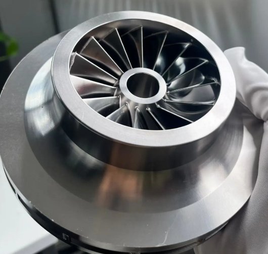
What Are Turbo Impellers?
A turbo impeller is a bladed rotor used in turbomachinery to create or absorb fluid momentum. The component usually includes blades, hub, shroud or open blade tips, bore, back face, nose profile and balancing features. Depending on the machine type, the impeller may be designed for air, nitrogen, natural gas, steam, exhaust gas, refrigerant or process gas.
For high-speed equipment, Turbo Impellers must be evaluated as aerodynamic parts and rotating mechanical parts at the same time. A small change in blade thickness, inlet angle, surface finish or tip clearance can influence pressure ratio, mass flow, surge margin, noise level and shaft vibration.
Common Types of Turbo Impellers
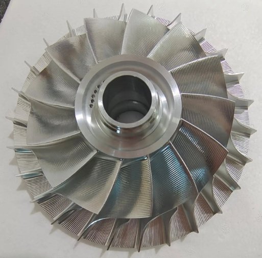
Centrifugal Compressor Impellers
Centrifugal compressor impellers convert shaft power into gas velocity and pressure rise. They are widely used in air compressors, process gas compressors, fuel cell air supply systems, HVAC chillers, pipeline equipment and industrial gas boosting systems.
- Open, semi-open and covered impeller configurations
- Backward-curved, radial or mixed-flow blade geometry
- Single-stage and multi-stage compressor designs
- Optimized inducer, exducer and diffuser matching
Radial Turbine Impellers
Radial turbine impellers, also called turbine wheels, extract energy from hot or expanding gas. They are commonly used in turbochargers, microturbines, waste heat recovery systems and small gas turbine assemblies.
- High-temperature alloy construction
- Fatigue-resistant blade root design
- Thermal expansion and creep resistance considerations
- Precision balancing for high rotational speed
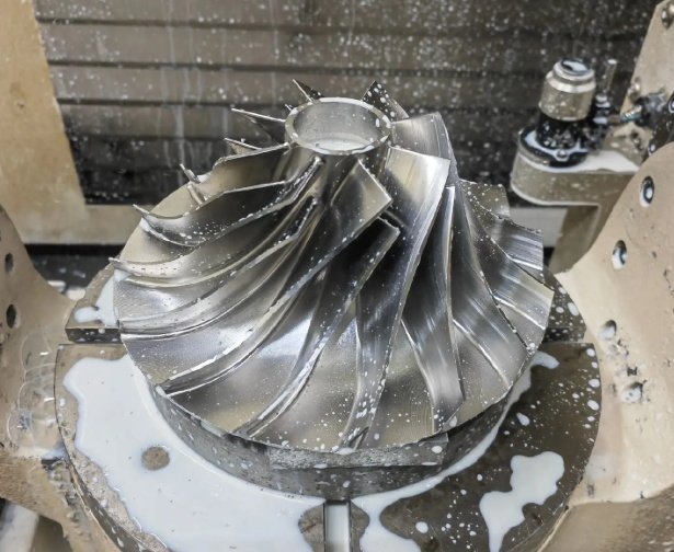
Turbocharger Compressor Wheels
Turbocharger compressor wheels are compact, lightweight turbo impellers designed for fast transient response, high pressure ratio and reliable high-cycle fatigue performance. Aluminum, titanium and advanced forged materials are commonly selected according to speed and temperature requirements.
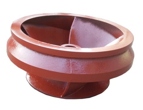
Industrial Blower and Fan Impellers
Industrial turbo impellers for blowers and high-speed fans are used in wastewater aeration, pneumatic conveying, fuel cell systems, combustion air supply, vacuum generation and process ventilation. The design priority is often a balance of flow capacity, pressure rise, acoustic behavior and energy consumption.
Engineering Parameters That Define Impeller Performance
Correct impeller selection requires more than matching an outside diameter. Engineers normally review operating speed, gas properties, pressure ratio, blade geometry, stress margin and rotor dynamics before confirming a design. The following parameters are commonly used when specifying or comparing turbo impellers.
| Parameter | Why It Matters | Typical Engineering Consideration |
|---|---|---|
| Outer diameter | Influences tip speed, pressure rise and stress level | Must match aerodynamic target and mechanical speed limit |
| Blade inlet angle | Affects incidence loss and operating range | Matched to inlet guide vane or upstream flow condition |
| Blade exit angle | Controls work input, pressure ratio and efficiency | Optimized with diffuser or volute design |
| Tip clearance | Impacts leakage, efficiency and rubbing risk | Adjusted for thermal growth and bearing movement |
| Surface roughness | Changes boundary layer behavior and loss | Lower roughness is preferred for high-efficiency compressors |
| Balance grade | Reduces vibration and bearing load | Specified according to operating speed and rotor mass |
| Material strength | Determines burst margin and fatigue life | Verified by stress analysis, heat treatment and inspection |
For applications where efficiency, pressure ratio and rotor stability are critical, impeller geometry should be reviewed together with diffuser, volute, shaft, bearings and seals rather than as an isolated component.
Materials for Turbo Impellers
Material selection depends on rotational speed, gas temperature, corrosion risk, density target, fatigue requirement and manufacturing route. A lightweight aluminum impeller may be ideal for a high-speed compressor, while a nickel-based superalloy may be necessary for a turbine wheel exposed to hot exhaust gas.
| Material | Common Use | Key Advantages | Engineering Notes |
|---|---|---|---|
| 7075 aluminum alloy | High-speed compressor wheels and blower impellers | Low density, good machinability, high strength-to-weight ratio | Often heat treated and anodized for improved durability |
| 2618 aluminum alloy | Turbocharger compressor wheels | Good thermal stability and fatigue resistance | Suitable for elevated compressor outlet temperatures |
| Ti-6Al-4V titanium alloy | High-speed, lightweight or corrosion-sensitive impellers | High strength, low density, good corrosion resistance | Requires controlled machining parameters due to low thermal conductivity |
| 17-4PH stainless steel | Process gas, moisture or mildly corrosive environments | Strength, corrosion resistance and heat treatability | Common for durable industrial impeller applications |
| Inconel 713C, 718 or similar alloys | Turbine wheels and hot gas applications | High-temperature strength, oxidation resistance and creep resistance | Machining and inspection requirements are more demanding |
Precision Manufacturing and Machining Capabilities
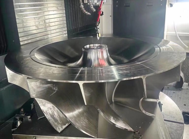
Turbo impeller manufacturing usually combines aerodynamic modeling, material preparation, CNC machining, heat treatment, surface finishing, dimensional inspection and dynamic balancing. The manufacturing route must preserve blade geometry while controlling residual stress and runout.
For complex blade channels, 5-axis CNC milling is commonly used to machine inducer curves, splitter blades, hub surfaces and exducer profiles with consistent tool engagement. Depending on the design, roughing, semi-finishing and finishing operations may use ball-end cutters, tapered end mills, barrel tools or custom form tools.
Key Machining Considerations
- Stable fixturing to prevent blade distortion during high-speed milling
- Toolpath optimization to reduce chatter marks on thin blades
- Controlled stock allowance between roughing and finishing operations
- In-process probing to verify bore location, datum surfaces and blade height
- Deburring of leading edges and trailing edges without changing aerodynamic shape
- Surface finishing by polishing, blasting, coating or anodizing when required
Typical Manufacturing Tolerances
| Feature | Typical Control Range | Purpose |
|---|---|---|
| Bore diameter | According to shaft fit requirement, commonly within micrometer-level control for precision assemblies | Ensures concentricity, torque transmission and repeatable assembly |
| Blade profile deviation | Defined by CAD model and inspection plan | Maintains aerodynamic performance |
| Axial runout | Controlled according to rotor stack requirement | Reduces vibration and seal clearance variation |
| Radial runout | Controlled according to speed and bearing system | Improves balance repeatability and rotor stability |
| Surface roughness | Specified by flow path and application | Reduces friction loss and contamination buildup |
Machining data that helps prevent manufacturing delays
For accurate production review, buyers should provide a 3D CAD model, 2D drawing, material grade, heat treatment specification, surface finish requirement, balance grade, maximum operating speed, operating temperature, working gas, coating requirement and inspection standard. If the project involves reverse engineering, a sample impeller, rotor assembly data and measured machine performance can reduce design uncertainty.
Quality Control, Balancing and Validation
Because turbo impellers are rotating safety-critical components, inspection must confirm both geometry and mechanical integrity. A typical validation plan may include incoming material certification, chemical composition review, mechanical property verification, coordinate measuring machine inspection, optical blade scanning, surface roughness measurement, hardness testing, non-destructive testing and dynamic balancing.
Dynamic balancing is especially important. An impeller that appears dimensionally correct may still create excessive vibration if mass distribution is not controlled. Balance correction can be achieved through controlled material removal at approved locations, never by changing functional blade profiles.
- Material certificate review for traceability
- CMM or optical scanning inspection against CAD model
- Dye penetrant testing for surface cracks when required
- X-ray or ultrasonic inspection for cast or high-risk components
- Hardness and heat treatment verification
- Low-speed and high-speed dynamic balancing according to the rotor class
- Overspeed testing for selected high-risk or high-speed applications
For many high-speed assemblies, balance quality grade is specified using recognized rotor balancing practices such as ISO 21940 principles. The final acceptance criterion should be based on operating speed, rotor mass, bearing type and permissible vibration level.
Real Engineering Problems Solved by Better Impeller Design
Turbo impeller performance issues often appear as higher energy consumption, unstable flow, elevated bearing temperature, blade cracking, rubbing, noise or vibration. In many cases, the root cause is not a single defect but a combination of aerodynamic mismatch, insufficient material margin and manufacturing variation.
Problem: High Vibration After Compressor Retrofit
A centrifugal blower retrofit using a replacement impeller showed a vibration level of 7.1 mm/s RMS near the drive-end bearing at rated speed. Inspection found that the bore concentricity, back-face runout and balance correction locations were outside the recommended design window. After machining a revised impeller with tighter datum control and two-plane dynamic balancing, vibration was reduced to 1.8 mm/s RMS under comparable operating conditions.
Problem: Excessive Power Consumption
In a 220 kW industrial air blower, the original impeller had worn leading edges and a roughened flow path. A replacement impeller with restored blade geometry, improved surface finish and corrected tip clearance produced a measured power reduction of 5.6% at the same duty point. The reported isentropic efficiency increased by 3.2 percentage points based on inlet pressure, outlet pressure, temperature and flow measurement.
Problem: Short Blade Fatigue Life
For a high-speed compressor wheel operating through frequent start-stop cycles, fatigue cracks were observed near the blade root. Finite element review indicated a local stress concentration caused by a sharp transition radius. The revised impeller used a larger fillet, controlled machining marks and verified material heat treatment, improving fatigue margin without changing the target flow rate.
Specification Guide for Engineers and Buyers
A clear specification reduces procurement risk and helps the manufacturing team confirm feasibility before production. For custom turbo impellers, buyers should define both performance requirements and acceptance criteria.
| Specification Item | Information to Provide | Why It Is Important |
|---|---|---|
| Machine type | Compressor, turbine, blower, turbocharger or pump | Determines design assumptions and inspection focus |
| Operating speed | Rated speed, maximum continuous speed and overspeed condition | Defines stress level and balance requirement |
| Working fluid | Air, gas, steam, refrigerant or corrosive medium | Influences material, coating and corrosion control |
| Temperature range | Inlet, outlet and transient temperature data | Supports thermal growth and material selection |
| Performance target | Flow rate, pressure ratio, head or efficiency target | Guides aerodynamic design or verification |
| Interface dimensions | Bore, keyway, thread, face, shaft fit and nut interface | Ensures compatibility with the rotor assembly |
| Inspection requirement | CMM report, material certificate, NDT report or balance report | Defines acceptance documentation |
Buyer viewpoint: how to compare turbo impeller suppliers
Procurement teams should compare suppliers by engineering support, machining capability, material traceability, inspection equipment, balancing experience and ability to interpret application data. The lowest unit price can become expensive if rework, vibration troubleshooting, downtime or repeated balancing is required.
Engineer viewpoint: when a custom impeller is better than a catalog replacement
A custom impeller is often preferred when the original part is obsolete, operating conditions have changed, the machine has recurring vibration, a higher efficiency target is required, or the impeller must match a modified volute, diffuser, shaft or bearing system. Custom design also allows geometry adjustments for flow range, surge margin, material upgrade and life extension.
Applications and Operating Environments
Turbo impellers are used in equipment where compact energy transfer, high rotational speed and controlled fluid dynamics are required. Application conditions can vary significantly, so impeller selection should always consider the complete rotor and flow system.
- Centrifugal air compressors for industrial plants
- Process gas compressors for chemical and energy facilities
- Turbochargers for automotive, marine and power generation engines
- High-speed blowers for wastewater aeration and pneumatic conveying
- Fuel cell air compressors and hydrogen-related balance-of-plant equipment
- Microturbines and waste heat recovery systems
- Vacuum systems, gas boosters and specialized rotating machinery
In corrosive, high-temperature or particle-laden environments, material compatibility and surface protection should be reviewed early. Coatings, anodizing, passivation or erosion-resistant surface treatments may improve durability, but they must not compromise blade clearance or balance condition.
Design Review Checklist Before Production
Before releasing a turbo impeller to manufacturing, a structured engineering review can prevent costly nonconformance and performance loss.
- Confirm aerodynamic geometry against the required flow and pressure target.
- Check centrifugal stress at maximum operating speed and overspeed condition.
- Verify material strength, fatigue properties and heat treatment condition.
- Review blade thickness, fillet radius and hub transition for stress concentration.
- Confirm shaft fit, torque transmission method and assembly sequence.
- Define datum structure for machining and inspection.
- Specify surface finish on aerodynamic flow surfaces.
- Confirm acceptable balancing method and correction zones.
- Define inspection documents required for shipment and acceptance.
Why Precision Matters for Turbo Impellers
Turbo impellers operate in a narrow window where aerodynamic efficiency, structural strength and rotor dynamics overlap. A well-designed and accurately machined impeller can help reduce vibration, improve energy efficiency, extend bearing life and stabilize machine operation. A poorly controlled impeller can create recurring field issues even if it fits the shaft dimensionally.
For sourcing decisions, the most reliable approach is to evaluate the complete package: design understanding, material selection, machining process, dimensional inspection, balancing practice and application knowledge. When these elements are aligned, turbo impellers can deliver measurable improvements in performance, reliability and lifecycle cost.