An axial impeller is a rotating blade component designed to move fluid primarily in the direction parallel to the shaft. Compared with radial impellers that discharge fluid outward toward the vessel wall, an Axial Flow Impeller generates strong top-to-bottom circulation, making it suitable for blending, heat transfer, suspension, aeration support and low-to-medium viscosity process mixing.
Our axial impellers are manufactured for industrial mixers, agitators, circulation equipment and selected pump applications where stable flow, mechanical reliability and process repeatability are critical. Available configurations include pitched blade impellers, hydrofoil impellers, marine propeller impellers and custom axial flow turbine designs.
Product Overview
Axial impellers are selected when engineers need high pumping capacity, efficient bulk flow and reduced localized shear. The blade angle, blade profile, diameter-to-tank ratio, hub design and rotational speed directly affect pumping number, power number, flow pattern and mixing time.
- Flow direction: parallel to the shaft, typically downward or upward depending on installation
- Common blade angles: 30°, 35°, 40° and 45° pitched blade designs
- Typical impeller-to-tank diameter ratio: 0.25 to 0.50 depending on duty
- Operating range: low-viscosity liquids to moderate-viscosity slurries
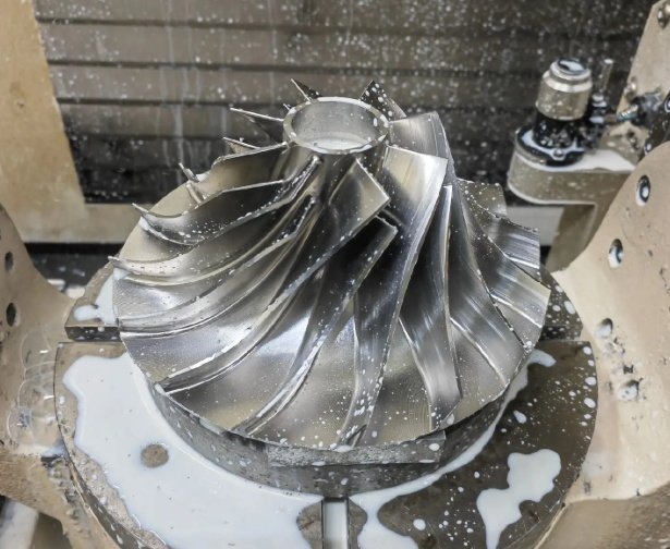
- Manufacturing options: welded, cast, machined, fabricated or dynamically balanced assemblies
How an Axial Flow Impeller Works
An axial flow impeller creates a large-volume circulation loop inside a tank or vessel. In a down-pumping configuration, liquid is pushed from the impeller toward the tank bottom, then rises along the vessel wall and returns to the impeller zone. This circulation pattern improves macro-mixing and helps reduce dead zones.
In an up-pumping configuration, the axial impeller pulls liquid from below and discharges it upward. This arrangement can be useful when vortex control, gas dispersion assistance or surface turnover is required.
| Design Parameter | Engineering Influence | Typical Consideration |
|---|---|---|
| Blade Pitch | Controls axial pumping strength and power draw | Higher pitch increases flow but may increase torque |
| Impeller Diameter | Affects circulation rate and mixing time | Larger diameter improves flow at lower speed |
| Blade Profile | Impacts efficiency, shear and cavitation tendency | Hydrofoil profiles reduce power consumption |
| Clearance from Tank Bottom | Affects solids suspension and bottom sweeping | Commonly 0.3D to 1.0D depending on tank geometry |
Types of Axial Impellers
Pitched Blade Axial Impeller
The pitched blade axial impeller is one of the most widely used industrial mixing designs. It normally uses three or four flat blades mounted at a fixed angle to the hub. It is robust, cost-effective and suitable for blending, dissolution, heat transfer and general liquid agitation.
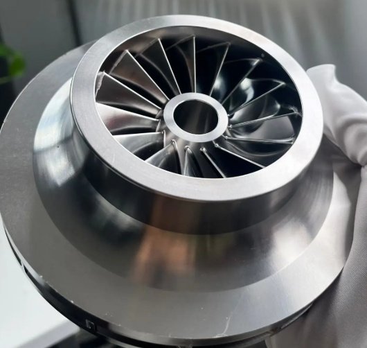
Hydrofoil Axial Impeller
A hydrofoil axial impeller uses streamlined blades to deliver high flow with lower power consumption. It is often selected for large tanks, continuous processes and applications where energy efficiency is important.
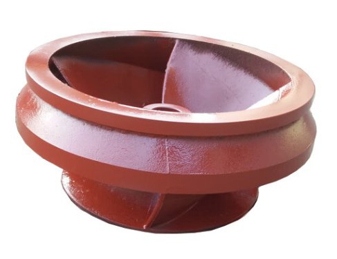
Marine Propeller Impeller
Marine propeller impellers are compact axial flow designs commonly used for low-viscosity liquids, portable mixers, chemical dosing tanks and circulation duties. They provide fast fluid movement but may not be ideal for heavy slurry or highly viscous media.
Custom Axial Flow Turbine
For demanding processes, custom axial flow turbines can be designed with reinforced blades, replaceable wear parts, special blade curvature or split construction for installation through manways.
Axial Impeller vs Radial and Mixed Flow Impellers
Selecting the correct impeller type depends on flow objective, viscosity, tank geometry, shear sensitivity and solids behavior. The comparison below helps buyers and process engineers evaluate whether an axial impeller is the right solution.
| Impeller Type | Primary Flow Direction | Best For | Limitations |
|---|---|---|---|
| Axial Impeller | Parallel to shaft | Bulk blending, suspension, heat transfer, circulation | Less suitable when intense localized shear is required |
| Radial Impeller | Perpendicular to shaft | Gas dispersion, high shear, emulsification | Higher power draw and lower bulk circulation efficiency |
| Mixed Flow Impeller | Combination of axial and radial | Balanced circulation and moderate shear | Requires careful selection for process-specific results |
For large-volume tanks, an axial flow design can often reduce mixing time while lowering energy use. In many water-like liquid blending applications, a hydrofoil axial impeller can deliver comparable circulation at 20% to 40% lower power than a conventional flat-blade turbine, depending on tank dimensions and operating speed.
When should I choose an axial impeller instead of a radial impeller?
Choose an axial impeller when the process target is large-scale circulation, rapid turnover, uniform concentration, heat transfer or keeping solids suspended. Choose a radial impeller when the process requires intense shear, gas breakup or strong local turbulence.
Engineering Performance and Application Results
In practical mixing projects, axial impellers are frequently used to solve uneven concentration, sediment buildup, long batch blending time and temperature stratification. Performance depends on correct sizing, speed, baffle design and vessel geometry.
Example engineering result: in a 12 m³ blending tank containing a low-viscosity chemical solution, replacing a small radial turbine with a larger hydrofoil axial impeller reduced batch homogenization time from approximately 18 minutes to 11 minutes. Motor load decreased by about 22% after speed and impeller diameter were optimized. Actual results vary by fluid properties, tank shape and mixing objective.
For solid suspension duties, the impeller must generate enough bottom velocity to prevent settling. Engineers commonly evaluate just-suspended speed, particle size distribution, density difference, slurry concentration and tank bottom geometry before finalizing the axial impeller design.
Materials, Machining and Manufacturing Options
We manufacture axial impellers using materials selected for corrosion resistance, mechanical strength, hygiene requirements and wear performance. Precision machining and controlled fabrication help ensure stable operation, reduced vibration and longer service life.
- Stainless steel: SS304, SS316, SS316L, duplex stainless steel for chemical and sanitary environments
- Carbon steel: economical option for non-corrosive industrial processes
- Special alloys: Hastelloy, titanium or nickel alloys for aggressive media
- Coated designs: rubber lining, PTFE coating or wear-resistant coating for abrasive or corrosive service
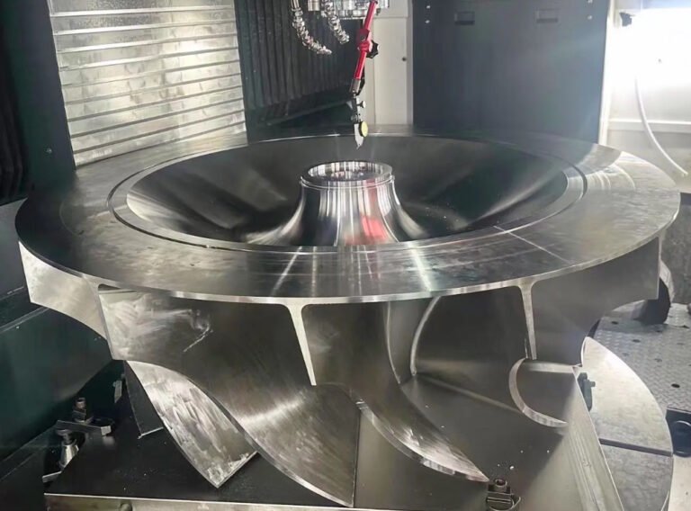
- Machining processes: CNC hub boring, keyway impeller machining, taper bore machining, blade trimming and balancing
Critical manufacturing controls include blade angle consistency, weld penetration, runout tolerance, surface finish, hub concentricity and dynamic balancing. For high-speed or large-diameter impellers, dynamic balancing is recommended to reduce bearing load and shaft vibration.
| Manufacturing Feature | Available Option | Buyer Benefit |
|---|---|---|
| Hub Connection | Straight bore, taper bore, keyed bore, split hub | Compatible with existing mixer shafts |
| Blade Construction | Welded, bolted, cast or machined | Matches duty, budget and maintenance plan |
| Surface Finish | Pickled, polished, passivated, coated | Improves cleanliness and corrosion resistance |
| Inspection | Dimensional check, weld inspection, balance test | Reduces installation and commissioning risk |
Can an axial impeller be custom machined for an existing shaft?
Yes. Custom machining can include bore diameter, keyway size, set screw position, taper fit, shaft shoulder clearance and split hub design. Buyers should provide shaft diameter, keyway standard, rotation direction, available installation space and operating speed.
Standard and Custom Specifications
Axial impellers can be supplied as standard components or engineered assemblies. The following table lists common specification ranges. Custom sizes are available for replacement, retrofit and new equipment projects.
| Specification | Typical Range | Customization Notes |
|---|---|---|
| Impeller Diameter | 100 mm to 3000 mm+ | Designed according to tank diameter and process duty |
| Blade Quantity | 2, 3, 4 or 6 blades | Selected by flow requirement and mechanical load |
| Blade Angle | 30° to 45° common | Other angles available for optimized pumping |
| Rotation | Clockwise or counterclockwise | Must match motor and gearbox direction |
| Operating Speed | Low speed to high speed, application dependent | Checked against vibration, cavitation and power limits |
| Connection | Weld-on, clamp-on, bolted, keyed, split hub | Designed for installation and maintenance access |
Selection Guide for Engineers and Buyers
The best axial impeller is not simply the largest or fastest option. It should be matched to fluid properties, vessel geometry and process requirements. Oversizing can increase shaft load and motor power, while undersizing can cause poor blending, settling or temperature gradients.
- Fluid data: viscosity, density, temperature, corrosiveness, solids content and particle size
- Tank data: diameter, liquid height, bottom shape, baffle arrangement and working volume
- Process target: blending time, heat transfer, solids suspension, gas-liquid contact or circulation
- Mechanical data: shaft diameter, motor power, gearbox speed, seal type and allowable torque
- Installation limits: manway size, lifting clearance, maintenance access and cleaning requirements
For replacement projects, buyers should also provide photos, existing impeller diameter, blade width, blade pitch, hub dimensions, shaft connection details and any observed failure mode such as cracking, erosion, corrosion or vibration.
What information helps confirm the correct axial impeller design?
Useful information includes tank volume, tank diameter, liquid height, fluid viscosity, density, solids percentage, target mixing time, motor power, shaft speed, shaft diameter, rotation direction and material requirements. For retrofit projects, drawings or measured dimensions of the existing impeller are highly valuable.
Common Applications
Axial impellers are used across industries where efficient fluid circulation and predictable mixing performance are required. Their high-flow, low-shear characteristics make them especially useful in processes that need uniformity without excessive product damage.
- Chemical blending and dilution tanks
- Water and wastewater treatment basins
- Food and beverage mixing with sanitary material options
- Pharmaceutical and biotech process vessels
- Paint, coating and additive premixing
- Mining slurry suspension and leaching tanks
- Heat transfer tanks and temperature equalization systems
- Crystallization, precipitation and neutralization processes
Quality Control and Testing
Each axial impeller can be inspected according to project requirements before shipment. For demanding applications, inspection documentation may include material certificates, dimensional reports, weld inspection records, balance reports and surface treatment records.
- Dimensional verification of diameter, blade angle, bore and keyway
- Visual and weld inspection for fabricated impellers
- Static or dynamic balancing according to speed and diameter
- Surface finishing inspection for sanitary or corrosion-resistant service
- Packaging protection for machined surfaces, polished blades and coated components
Proper quality control reduces the risk of vibration, shaft misalignment, seal wear and premature bearing failure. For large agitators, balanced impeller assemblies are particularly important because even small geometric deviations can create significant rotating forces at operating speed.
Why Source Axial Impellers from an Engineering Manufacturer
Buyers need more than a catalog part when the process involves strict mixing targets, corrosive fluids, heavy-duty operation or equipment retrofit. An engineering manufacturer can review duty conditions, recommend blade geometry, confirm manufacturability and provide machining details that match the mixer shaft and vessel layout.
Our axial impeller supply capability covers standard replacement parts, OEM mixer components and custom-engineered impellers for industrial process equipment. Whether the requirement is a compact marine propeller or a large-diameter hydrofoil axial flow impeller, the focus is consistent: reliable circulation, efficient power use and mechanically sound operation.