
Flange Machining Services
At XCM, we deliver end-to-end metal machining solutions engineered to meet the most demanding specifications across oil & gas, aerospace, automotive, medical, electronics, and industrial sectors. Our state-of-the-art facility combines advanced CNC technology with decades of engineering expertise to transform your designs into high-performance metal components—on demand, custom manufacturing.
- Fast prototype & low MOQ support
- Tight tolerance up to +0.002mm
- Surface finishing available
- Engineering review before production
Flange Machining Capabilities
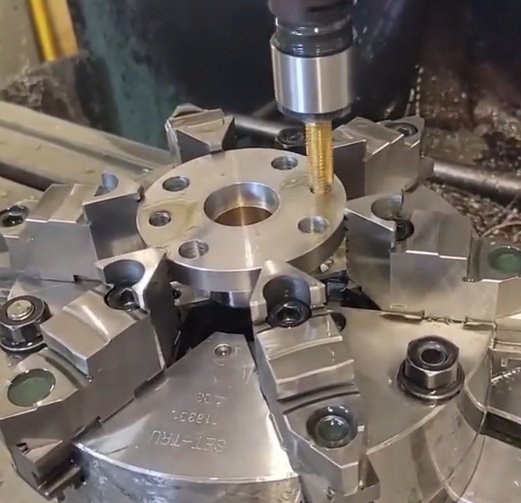
Rotary Machining Operations
CNC turning
Typical purpose: Machine OD, ID, hub, shoulder, chamfer, and face geometry
Key controlled features: Concentricity, flatness, parallelism, runout, surface finish
Flange facing
Typical purpose: Restore or produce gasket contact surfaces
Key controlled features: Raised face height, serration, Ra value, face runout
Precision Hole Making
Boring
Typical purpose: Open or finish internal diameters for pipe, nozzle, shaft, or equipment fit
Key controlled features: Bore size, roundness, alignment to face and bolt circle
CNC drilling
Typical purpose: Produce bolt holes and mounting holes
Key controlled features: PCD, hole diameter, angular spacing, perpendicularity
Thread & Groove Processes
Tapping and thread milling
Typical purpose: Machine threaded holes for studs, plugs, lifting points, or instruments
Key controlled features: Thread class, depth, position, engagement length
Grooving
Typical purpose: Machine RTJ grooves, O-ring grooves, gasket seats, and relief grooves
Key controlled features: Groove width, depth, radius, side angle, bottom finish
Shaping & Profiling
Milling
Typical purpose: Produce flats, slots, keyways, ports, pockets, or special profiles
Key controlled features: Profile accuracy, location, edge break, surface finish
Profile Milling
Typical purpose: Form custom contours and complex geometric features
Key controlled features: Dimensional precision, surface quality, positional tolerance
Component Restoration
Repair machining
Typical purpose: Correct damaged or distorted flange surfaces
Key controlled features: Minimum material removal, sealing face recovery, residual thickness
Surface Refinishing
Typical purpose: Restore functional surfaces and geometric integrity
Key controlled features: Flatness, parallelism, surface roughness, dimensional restoration
Quality & Control Features
Dimensional Inspection
Typical purpose: Verify size, position, and geometric compliance
Key controlled features: Tolerance adherence, alignment, concentricity, symmetry
Surface Quality Control
Typical purpose: Ensure finish and texture meet functional requirements
Key controlled features: Ra value, smoothness, flaw detection, consistency
Flange Machining: Tolerances, Surface Finish, and Quality Controls
Flange Machining Tolerances
- Dimensional tolerances per ASME, EN, DIN, JIS, or customer drawing requirements
- Bore diameter and ID tolerances for precise fitting
- OD and face runout control for sealing integrity
- Parallelism and flatness of flange sealing faces
- PCD (Pitch Circle Diameter) and hole position tolerances
- Groove depth, width, and profile tolerances for RTJ, O-ring, and gasket seats
- Concentricity and alignment between bore, hub, and flange face
Surface Finish Requirements
- Ra roughness values specified for gasket contact surfaces
- Spiral serrated / phonographic finish for standard gasket seating
- Smooth finish for metal-to-metal sealing and RTJ flanges
- Consistent surface texture across entire sealing face
- Edge break and deburring on all machined surfaces
- ID/OD surface finish for welding and assembly compatibility
Quality Controls & Inspection
- Full dimensional inspection using calibrated tools
- Surface roughness testing (Ra measurement)
- Visual inspection for defects, scratches, and imperfections
- Material verification and traceability documentation
- Geometric tolerance verification (runout, flatness, perpendicularity)
- Certification of conformance to standards and project specs
- Pre‑shipping quality check for fit, function, and sealing performance
Standard and Custom Flange Machining
Common flange machining requirements
- Machining raised face, flat face, tongue-and-groove, male-and-female, and ring-type joint faces
- Boring inner diameters for pipe, hub, valve, nozzle, or equipment fit-up
- Machining bolt circle diameter, pitch circle diameter, bolt holes, counterbores, and tapped holes
- Turning outside diameters, hubs, shoulders, steps, tapers, chamfers, and weld preps
- Cutting RTJ grooves, O-ring grooves, gasket grooves, and sealing recesses
- Refacing worn, corroded, distorted, or damaged flange faces
- Machining non-standard flanges from customer drawings, 3D models, samples, or reverse-engineered dimensions
Machining can be specified to match standards such as ASME, ANSI, EN, DIN, JIS, API, MSS, or a project-specific engineering drawing. For custom flanges, dimensional priorities are normally defined by gasket type, pressure class, mating part, bolt pattern, and service temperature.
Flange Types, Face Forms, and Standards Supported
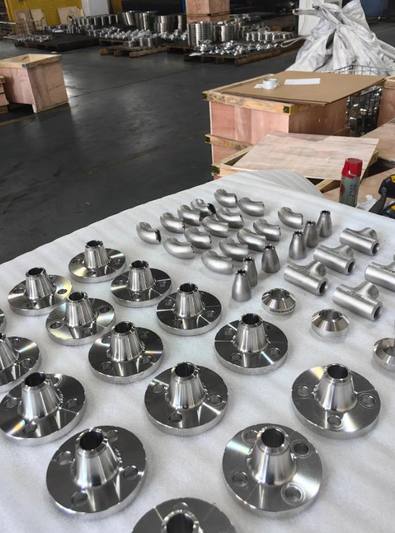
Flange types
- Weld neck flanges
- Slip-on flanges
- Blind flanges
- Socket weld flanges
- Threaded flanges
- Lap joint flanges
- Orifice flanges
- Long weld neck flanges
- Reducing flanges
- Custom adapter flanges and transition flanges
- Heat exchanger, vessel, nozzle, pump, compressor, and valve flanges
Face forms and sealing features
- Raised face flange machining
- Flat face flange machining
- RTJ flange groove machining
- Tongue-and-groove flange machining
- Male-and-female flange machining
- Serrated gasket surface machining
- O-ring groove machining
- Spiral phonographic finish for gasket seating
Applicable standards and drawing references
- ASME B16.5: Pipe flanges and flanged fittings up to NPS 24
- ASME B16.47: Large diameter steel flanges
- EN 1092-1: European circular steel flanges
- API and MSS references: Oil, gas, pipeline, valve, and process industry flange requirements
More
- JIS B2220: Japanese standard steel pipe flanges
- DIN flange standards: Metric flange dimensions and legacy European requirements
- Customer engineering drawing: Non-standard flange geometry, special tolerances, and project-specific acceptance criteria
Flange machining is often required because field installation, welding, corrosion, thermal cycling, or previous fabrication has introduced dimensional error. In these cases, the goal is not only to remove material, but to use measurable corrective machining to restore fit, sealing, and alignment.
| Engineering issue | Machining approach | Typical measurable result |
|---|---|---|
| Raised face distortion after welding | Indicate the bore, skim cut the sealing face, and re-establish face parallelism | Example: face runout reduced from 0.38 mm to 0.05 mm on a medium-size weld neck flange |
| Corroded gasket surface on process flange | Remove minimum stock, re-machine serrated finish, verify remaining raised face height | Example: 0.25 mm material removal restored continuous gasket contact without replacing the flange |
| Bolt-hole misalignment on fabricated flange ring | Re-reference from center bore, correct PCD, and re-machine holes or counterbores where allowed | Example: assembly interference eliminated after correcting angular hole position and deburring |
| RTJ groove wear or impact damage | Inspect groove geometry, machine to standard profile if remaining material allows, verify groove depth | Example: metal ring gasket seating restored with controlled groove width and bottom finish |
| Large flange face not parallel to mounting side | Machine both faces in controlled setups and verify total indicator reading | Example: improved pump or vessel nozzle alignment during final assembly |
Data should always be interpreted according to flange size, material, code rules, corrosion allowance, minimum thickness, and engineering approval. When the flange is part of pressure-retaining equipment, repair machining may require a documented disposition before work begins.
A reliable flange machining order depends on clear technical information. A complete machining package reduces quotation uncertainty, prevents rework, and helps machining teams plan tooling, inspection, and material handling.
- Flange type, quantity, size, pressure class, and applicable standard
- 2D drawing, 3D model, standard reference, or sample part
- Material grade, heat treatment condition, and material certificate requirement
- Required face type: RF, FF, RTJ, tongue-and-groove, male-and-female, O-ring groove, or special profile
- Bore size, pipe schedule, hub dimensions, weld preparation, and chamfer requirements
- Bolt-hole quantity, diameter, PCD, counterbore, spotface, and thread specification
- Surface finish requirement for sealing faces and mounting faces
- Critical tolerances, GD&T callouts, inspection points, and documentation requirements
- Coating, marking, packing, and preservation requirements
Recommended drawing notes for custom flanges
Useful drawing notes include the governing standard, pressure class, gasket type, surface finish symbol, bolt-hole angular reference, datum structure, minimum thickness after machining, edge break requirement, material grade, heat treatment condition, NDT requirement, and whether dimensions apply before or after coating.
- Review drawing, standard, material, and inspection requirements
- Confirm machining allowance and blank condition
- Create CNC program, tooling plan, and setup strategy
- Rough machine OD, ID, hub, and faces where required
- Finish machine sealing face, bore, grooves, and mounting features
- Drill, tap, counterbore, or mill bolt-hole features
- Deburr, clean, inspect, and mark the component
- Prepare inspection records, material documents, and packing
Documentation requirements depend on the industry and risk level. For general industrial flanges, dimensional inspection and material confirmation may be sufficient. For oil and gas, petrochemical, power generation, pressure vessel, and offshore projects, more detailed documentation is often required.
- Dimensional inspection report
- Surface roughness measurement report
- Material test report, such as EN 10204 3.1 where applicable
- Positive material identification report
- Hardness test report
- Thread inspection record
- CMM report for bolt circle and complex geometry
- NDT reports such as PT, MT, UT, or RT when specified
- Heat treatment record, coating record, or pressure test certificate if part of the supply scope
- Certificate of conformity
When a flange machining job may need engineering approval
Engineering approval is recommended when repair machining changes pressure boundary thickness, raised face height, RTJ groove depth, corrosion allowance, code compliance, or mating compatibility. Approval is also important when a damaged flange is being recovered instead of replaced.
Small design and procurement decisions can significantly affect machining time, inspection effort, and total cost. The following points help engineers and buyers specify flanges that are easier to manufacture without compromising function.
- Define the gasket type before specifying face finish or groove geometry.
- Use recognized flange standards where possible instead of redrawing standard dimensions.
- Avoid unnecessary tight tolerances on non-functional outside diameters or cosmetic surfaces.
- Specify datum references for bolt circle, bore, and sealing face to prevent inspection disagreement.
- Confirm whether dimensions are required before coating, after coating, or after heat treatment.
- Allow sufficient machining stock on flame-cut, forged, cast, or welded blanks.
- For large-diameter flanges, consider handling points, lifting holes, and machine envelope limits.
- For stainless and nickel alloy flanges, plan tooling and speeds to reduce work hardening and surface tearing.
- For repair machining, measure remaining thickness before deciding how much material can be removed.
- For matched flange pairs, machine and inspect critical faces as a set when alignment is essential.
Well-defined flange machining specifications help reduce leakage risk, shorten assembly time, and improve interchangeability between mating components. The highest-value specifications are usually the ones tied directly to sealing, alignment, pressure integrity, and field installation.
Materials and Application Environments
Flange materials are selected according to pressure, temperature, corrosion risk, welding requirements, and industry codes. In machining, material grade affects cutting speed, tooling, distortion control, surface finish, and inspection planning. For regulated industries, material traceability is often as important as dimensional accuracy.
| Material group | Typical grades | Machining considerations |
|---|---|---|
| Carbon steel | A105, A350 LF2, S235, S355, C22.8 | Cost-effective for general pressure service; check face finish and corrosion allowance |
| Stainless steel | 304, 304L, 316, 316L, 321, 347 | Requires control of work hardening, tool condition, and heat generation |
| Duplex and super duplex | 2205, 2507, UNS S31803, UNS S32750 | Used for chloride environments; machining must manage toughness and heat input |
| Alloy steel | F11, F22, 4140, 42CrMo4, Cr-Mo grades | Often used in high-temperature or high-strength applications; hardness affects tooling |
| Nickel alloys | Inconel 625, Inconel 718, Hastelloy C276, Monel 400 | Requires rigid setups, sharp tooling, and conservative cutting data |
| Aluminum and non-ferrous alloys | 6061, 6082, bronze, brass, copper alloys | Useful for lightweight, electrical, marine, or low-pressure applications |
For pressure boundary components, machining should not be planned independently from heat treatment, welding, coating, hydrostatic testing, or code inspection. Face allowance, final thickness, and marking requirements should be reviewed before metal removal.