Reducing Flanges are pipe flanges designed to connect a larger flange connection to a smaller pipe size without using a separate pipe reducer in many compact piping layouts. They are commonly used where space, weight, weld count, or installation time must be controlled while maintaining a bolted flange joint that matches the required pressure class, facing type, bolt pattern, and material specification.
A reducing flange has the outside diameter, bolt circle, bolt holes, and facing dimensions of the larger nominal flange size, while the bore is machined to suit the smaller pipe size. This makes it useful for pumps, compressors, vessels, skid-mounted systems, process modules, water treatment equipment, chemical lines, oil and gas piping, and utility services where a size transition is needed directly at a flanged connection.
Our reducer flange supply covers standard and project-specific requirements, including ASME B16.5 reducing flange configurations, raised face, flat face, ring type joint, custom bore, special facing finish, NACE material options, and full documentation for industrial procurement.
What Is a Reducing Flange?
A reducing flange, also called a reducer flange or pipe flange reducer, is a bolted flange component that allows a smaller pipe to be connected to a larger mating flange. Unlike a standard flange, its nominal flange size and pipe bore size are different. For example, a 6 inch x 4 inch Class 300 reducing flange may have the flange outside diameter and bolt pattern of a 6 inch Class 300 flange, but its bore is machined for a 4 inch pipe.
The design is especially valuable when the pipe route does not have enough straight length for a separate reducer fitting, flange, and spool piece. In a typical 6 inch to 4 inch process line, using a reducing flange can reduce the installed length by approximately 120 mm to 250 mm, depending on pressure class, wall schedule, and fitting geometry. It may also remove one circumferential weld compared with some reducer-and-flange arrangements, improving fabrication efficiency and reducing inspection points.
| Feature | Engineering Purpose |
|---|---|
| Large flange outside diameter | Matches the mating flange, valve, pump nozzle, vessel nozzle, or equipment connection |
| Smaller machined bore | Fits the smaller pipe size or required inside diameter |
| Standard bolt circle | Allows installation with standard bolting for the selected nominal flange size and class |
| Raised face, flat face, or RTJ facing | Matches gasket type and sealing requirements |
| Custom taper or transition bore | Helps manage turbulence, pressure drop, and flow disturbance when specified |
Available Types of Reducing Flanges
The correct flange type depends on pressure rating, pipe wall thickness, service temperature, welding method, inspection requirements, and whether the system is permanent, threaded, or socket welded.
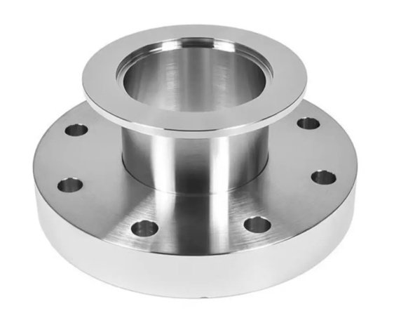
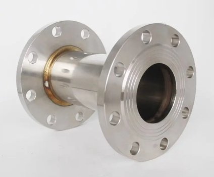
Weld Neck Reducing Flange
A weld neck reducing flange has a hub and is butt-welded to the smaller pipe. It is preferred for high-pressure, high-temperature, cyclic loading, hazardous fluids, and critical process piping. The tapered hub helps distribute stress more smoothly than many non-hubbed flange styles.
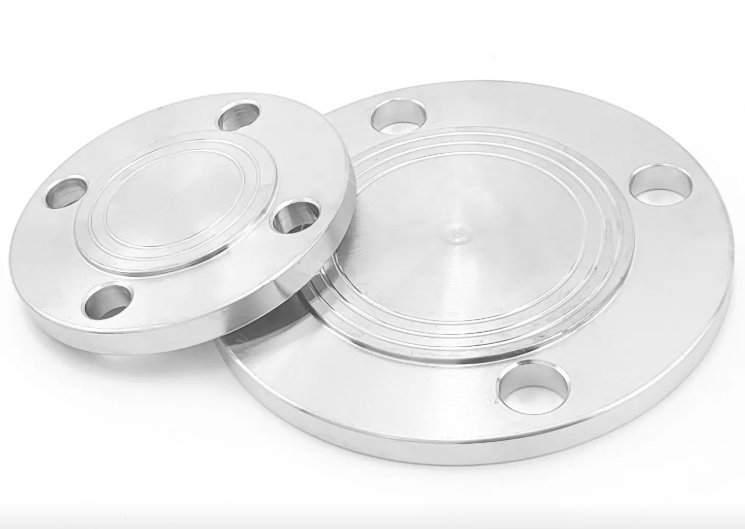
Slip On Reducing Flange
A slip on reducing flange slips over the smaller pipe and is normally fillet welded on both the inside and outside. It is commonly selected for lower to medium pressure utility systems, water lines, compressed air, and general industrial piping where alignment convenience and cost efficiency are important.
Threaded Reducing Flange
A threaded reducing flange uses an internal thread to connect with a smaller threaded pipe. It can be useful where welding is not permitted or practical. It is generally not recommended for severe cyclic, high-vibration, or high-temperature services unless the project specification allows it.
Socket Weld Reducing Flange
A socket weld reducing flange accepts the smaller pipe into a socket and is fillet welded around the outside. It is often used on small-bore high-pressure piping, instrument air, hydraulic lines, steam tracing, and auxiliary process connections.
Lap Joint Reducing Flange
A lap joint reducing flange is used with a stub end where frequent dismantling or alignment adjustment is required. It may be selected for stainless steel or alloy piping systems to reduce flange material cost when the backing flange does not contact the process fluid.
| Type | Typical Use | Key Advantage |
|---|---|---|
| Weld neck reducing flange | Critical process piping, high pressure, high temperature | Better stress distribution and weld integrity |
| Slip on reducing flange | Utility and general service piping | Easy installation and cost-effective fabrication |
| Threaded reducing flange | Non-welded small-bore connections | No field welding required |
| Socket weld reducing flange | Small-bore high-pressure systems | Compact and strong connection for small pipe sizes |
| Lap joint reducing flange | Systems requiring frequent disassembly | Rotatable flange alignment with stub end |
Standards, Dimensions and Pressure Classes
Reducing Flanges are typically manufactured according to recognized flange standards, with the reducing bore and transition details confirmed by the purchase specification or engineering drawing. Because reducing bore dimensions are not always fully defined in the same way as standard flanges, accurate pipe schedule, bore requirement, and mating flange data should be provided before production.
- ASME B16.5 for NPS 1/2 to NPS 24 flanges
- ASME B16.47 Series A or Series B for large diameter flange requirements when applicable
- EN 1092-1 for European PN-rated flange systems
- JIS, DIN, BS, MSS, or project-specific flange standards upon request
- Pressure classes commonly including Class 150, 300, 600, 900, 1500, and 2500
- PN ratings commonly including PN6, PN10, PN16, PN25, PN40, PN63, and PN100 where applicable
When ordering, the flange should be described by both the nominal flange size and the reducing bore pipe size. A clear description such as “8 inch x 6 inch Class 300 RF weld neck reducing flange, ASTM A105, bore for Sch 40 pipe” helps prevent dimensional ambiguity.
Information needed to confirm dimensions
- Nominal flange size and smaller pipe size
- Pressure class or PN rating
- Flange type: weld neck, slip on, threaded, socket weld, or lap joint
- Facing: RF, FF, RTJ, tongue and groove, or custom facing
- Pipe schedule or required bore diameter
- Material grade and applicable standard
- Required gasket standard and mating flange standard
- Any taper bore, back facing, serration, or special machining requirement
Materials for Reducing Flanges
Material selection should consider design pressure, operating temperature, corrosion allowance, fluid compatibility, weldability, sour service, and site standardization. We supply reducing flanges in carbon steel, low-temperature steel, stainless steel, duplex stainless steel, nickel alloy, and alloy steel grades.
| Material Group | Typical Grades | Common Applications |
|---|---|---|
| Carbon steel | ASTM A105, ASTM A350 LF2 | Oil and gas, water, steam, petrochemical, general process piping |
| Stainless steel | ASTM A182 F304, F304L, F316, F316L, F321, F347 | Chemical processing, food-grade utilities, marine, corrosive environments |
| Alloy steel | ASTM A182 F5, F9, F11, F22, F91 | High-temperature steam, refinery, power generation |
| Duplex stainless steel | ASTM A182 F51, F53, F55 | Chloride-containing service, offshore, seawater, chemical plants |
| Nickel alloy | Alloy 400, 600, 625, 825, C276 | Acid service, seawater, high-corrosion process conditions |
For sour service or aggressive process media, NACE MR0175 / ISO 15156 compliance, hardness control, heat treatment condition, and positive material identification can be specified to support engineering approval.
Facing, Gasket Compatibility and Sealing Performance
The sealing face of a reducing flange must match the mating flange and gasket system. Raised face flanges are widely used with spiral wound gaskets, compressed fiber gaskets, PTFE gaskets, and other soft or semi-metallic sealing products. Ring type joint reducing flanges are used for higher-pressure services where metal-to-metal gasket sealing is required.
- RF raised face: common in ASME Class 150 to Class 2500 piping systems
- FF flat face: often used with cast iron equipment or low-pressure applications
- RTJ ring type joint: used in high-pressure oil, gas, and refinery systems
- Custom serrated finish: available when surface roughness must meet gasket manufacturer requirements
Surface finish control is important. For many ASME raised face applications, a serrated finish in the range of 125 to 250 AARH is commonly specified, but final requirements should follow the project standard and gasket supplier recommendation.
Engineering Considerations Before Selecting Reducing Flanges
Although Reducing Flanges save space, they should be reviewed for hydraulic performance, stress concentration, nozzle loading, and maintenance accessibility. A reducing flange can create a more abrupt flow area change than a long tapered reducer unless a transition bore is specified. This may increase local turbulence and pressure loss in high-velocity service.
For clean water or utility service at moderate velocity, the impact is often acceptable. For compressor suction, pump suction, slurry, flashing liquid, erosive media, or multiphase flow, engineers may prefer a concentric or eccentric reducer with a longer transition to improve flow behavior.
- Check whether the smaller bore creates unacceptable pressure drop.
- Confirm whether flow direction and equipment nozzle requirements allow an abrupt reduction.
- Review gasket seating width when reducing bore is close to flange face geometry.
- Confirm weld neck bore matches pipe ID for full penetration welding.
- Check corrosion allowance and erosion risk at the transition area.
- Verify that flange rating is suitable at design temperature, not only ambient pressure.
Example engineering result in a skid-mounted system
In a packaged chemical dosing skid, a 4 inch equipment nozzle was connected to a 2 inch process line. Replacing a separate reducer spool with a 4 inch x 2 inch reducing flange shortened the connection envelope by approximately 180 mm and eliminated one field weld. The result was easier module installation, fewer weld inspection points, and improved clearance for adjacent instrumentation. The final selection was approved only after checking nozzle load limits, gasket seating, and flow velocity.
Manufacturing and Machining Capabilities
Reducing flange performance depends not only on material grade but also on forging quality, heat treatment, machining accuracy, bore alignment, facing finish, and inspection control. We manufacture and source reducer flanges from forged or plate materials according to the specified standard, application, size range, and pressure class.
The flange machining process typically includes rough turning, bore machining, hub profiling, bolt hole drilling, spot facing, gasket face machining, deburring, marking, inspection, and protective coating or packing. For weld neck reducing flanges, bore concentricity and weld bevel accuracy are critical because misalignment can affect fit-up quality and weld integrity.
Machining Features Available
- Custom reducing bore based on pipe schedule, inside diameter, or client drawing
- Tapered bore or blended transition to reduce abrupt flow disturbance
- Standard or special weld bevel preparation
- Raised face, flat face, RTJ groove, or special gasket face finish
- Back facing and spot facing for bolting contact control
- CNC drilling for accurate bolt hole location and repeatability
- Marking by stamping, low-stress marking, or laser marking where required
Dimensional inspections can include outside diameter, thickness, bolt circle diameter, bolt hole diameter, facing height, bore diameter, hub dimensions, bevel angle, serration quality, and flange face flatness. Tolerance control is especially important when the flange will be installed on prefabricated spools or modular equipment.
Inspection, Testing and Documentation
Industrial buyers often require traceable documentation to qualify Reducing Flanges for plant construction, maintenance shutdowns, EPC projects, or OEM equipment packages. Documentation can be supplied according to the purchase order and applicable project specification.
- Material Test Certificate according to EN 10204 3.1 or 3.2 when specified
- Chemical composition and mechanical property report
- Heat treatment record for applicable materials
- Positive Material Identification for alloy and stainless steel grades
- Ultrasonic testing, magnetic particle testing, liquid penetrant testing, or radiographic testing where required
- Dimensional inspection report
- Hardness test report for NACE or special service requirements
- Coating, marking, and packing inspection records
For carbon steel flanges, common surface protection includes black paint, anti-rust oil, zinc-rich coating, hot dip galvanizing, or project-specified coating. Stainless steel and nickel alloy flanges are usually protected with clean packing materials to avoid surface contamination.
Buyer checklist for procurement approval
- Confirm flange standard, size reduction, pressure class, and facing type.
- Provide pipe schedule or actual bore requirement instead of only nominal pipe size.
- Specify whether the bore transition is straight, stepped, tapered, or drawing-controlled.
- Confirm material grade, heat treatment, impact testing, and NACE requirements.
- State required certificates, NDE, PMI, and inspection hold points.
- Check compatibility with gasket, bolting, mating flange, and equipment nozzle.
Applications of Reducing Flanges
Reducing Flanges are used in new construction, plant modification, skid fabrication, equipment replacement, and maintenance projects. They are particularly useful when the designer needs a compact size transition directly at a flanged connection.
- Oil and gas production facilities
- Refinery and petrochemical process units
- Chemical dosing and chemical transfer systems
- Power generation and steam auxiliary systems
- Water treatment, desalination, and wastewater systems
- HVAC, chilled water, and fire protection pipelines
- Marine and offshore piping modules
- Pump, compressor, heat exchanger, and pressure vessel connections
- OEM equipment and prefabricated process skids
In maintenance projects, reducing flanges can help adapt existing equipment nozzles to modified pipe sizes without changing the entire piping layout. In modular construction, they help reduce spool length and simplify assembly where millimeters of clearance can affect installation.
How to Specify Reducing Flanges Correctly
A complete flange description helps avoid wrong bore, wrong bolt pattern, wrong facing, or gasket mismatch. The most reliable specification combines the flange standard, larger nominal flange size, smaller pipe size, pressure class, flange type, material, facing, pipe schedule, and inspection requirements.
Recommended format:
Reducing flange: 10 in x 8 in, ASME B16.5, Class 150, weld neck, raised face, ASTM A105, bore for 8 in Sch 40 pipe, 125-250 AARH serrated finish, MTC EN 10204 3.1, PMI if required.
For engineered systems, include the piping class, line number, design pressure, design temperature, corrosion allowance, gasket type, bolting grade, and any drawing-controlled dimensions. When the service is erosive, corrosive, high velocity, cyclic, or safety-critical, the flange selection should be reviewed by the responsible piping engineer before purchase.
Why Choose Precision-Machined Reducer Flanges
The value of a reducing flange is highest when it fits correctly the first time. A small bore error, bolt circle deviation, or facing mismatch can delay spool fabrication, hydrotesting, and site installation. Precision machining and documented inspection help reduce rework risk and support predictable project delivery.
- Standard and custom Reducing Flanges for ASME, EN, JIS, DIN, and project specifications
- Carbon steel, stainless steel, duplex, alloy steel, and nickel alloy options
- Custom bore machining for pipe schedule or specified inside diameter
- Support for RF, FF, RTJ, serrated, and special gasket face requirements
- Traceable material certificates and inspection documentation
- Suitable for EPC projects, OEM equipment, maintenance shutdowns, and prefabricated piping spools
When selected and manufactured correctly, Reducing Flanges provide a compact, reliable, and fabrication-friendly solution for pipe size transitions in industrial piping systems.