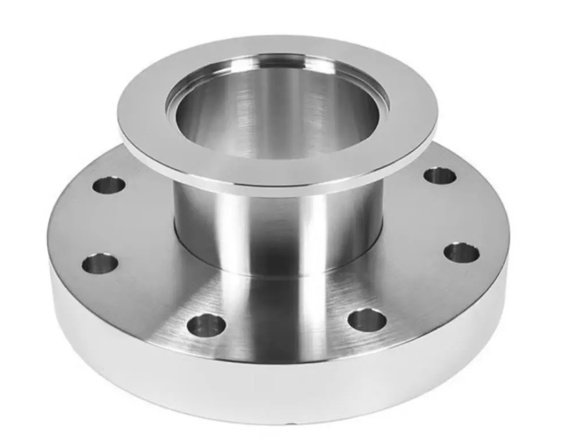
Orifice Flanges are specialized pipe flanges used with an orifice plate to measure the flow rate of liquids, gases, and steam through a pipeline. Unlike standard welding neck, slip-on, or threaded flanges, an orifice flange set includes pressure tap holes, jack screws, and dedicated machining features that allow a differential pressure transmitter to read the pressure drop across the orifice plate.
Designed for process plants, oil and gas pipelines, power generation, chemical systems, refinery units, water treatment facilities, and steam distribution networks, our Orifice Flanges are manufactured to recognized dimensional and pressure standards, including ASME B16.36, ASME B16.5, ASME B31.3 project requirements, and customer-specific engineering specifications.
What Are Orifice Flanges?
Orifice Flanges are installed in pairs with an orifice plate positioned between them. When fluid passes through the bore restriction of the orifice plate, velocity increases and static pressure decreases. The upstream and downstream tap holes on the flange body capture this pressure difference, allowing the flow rate to be calculated using differential pressure measurement principles.
A typical orifice flange assembly includes two matched flanges, one orifice plate, gaskets, studs, nuts, jack screws, and pressure tapping connections. For accurate metering, the internal bore, flange facing, tap location, gasket seating surface, and plate concentricity must be controlled carefully during machining and inspection.
Key Product Features
- Manufactured according to ASME B16.36 for orifice flange dimensions and pressure tap requirements.
- Available in welding neck, slip-on, and threaded designs depending on pipeline pressure, installation method, and maintenance requirements.
- Pressure classes commonly available from Class 300 to Class 2500, with project-specific ratings on request.
- Compatible with raised face, ring type joint, and other sealing configurations specified by the piping class.
- Precision-machined tap holes for stable differential pressure readings.
- Jack screws supplied to separate flange faces safely during orifice plate replacement or inspection.
- Material options include carbon steel, low-temperature carbon steel, stainless steel, duplex stainless steel, alloy steel, and nickel alloys.
- Suitable for flow measurement of steam, natural gas, compressed air, crude oil, refined products, cooling water, chemical media, and process fluids.
Orifice Flange Types
Selection depends on pressure rating, piping design code, installation environment, and maintenance access. The most common types are listed below.
| Type | Typical Application | Engineering Advantage |
|---|---|---|
| Welding Neck Orifice Flange | High-pressure, high-temperature, critical process lines | Excellent stress distribution and reliable weld integrity |
| Slip-On Orifice Flange | Lower-pressure utility and process service | Easier alignment and economical installation |
| Threaded Orifice Flange | Small-bore systems where welding is restricted | No field welding required; useful in maintenance lines |
| Raised Face Orifice Flange | General industrial pipelines | Common gasket sealing design for broad service conditions |
| RTJ Orifice Flange | High-pressure oil, gas, and refinery service | Metal-to-metal sealing for demanding pressure conditions |
Standards, Sizes, and Pressure Ratings
Our orifice flange products are commonly supplied according to ASME B16.36, which defines requirements such as flange dimensions, tap locations, jack screw arrangement, and pressure classes. Flange drilling and general dimensional compatibility are typically aligned with ASME B16.5 for sizes up to NPS 24.
| Standard | ASME B16.36, ASME B16.5, ASME B31.3 project piping requirements |
|---|---|
| Nominal Size Range | Commonly NPS 1 to NPS 24; larger engineered sizes available by drawing |
| Pressure Class | Class 300, 400, 600, 900, 1500, 2500 |
| Facing Options | RF, RTJ, FF when permitted by design specification |
| Tap Type | Flange taps, typically positioned according to ASME B16.36 |
| End Connection | Welding neck, slip-on, threaded |
| Documentation | MTC EN 10204 3.1, dimensional report, PMI report, NDT report, coating report when required |
Materials for Orifice Flanges
Material selection should consider operating temperature, pressure, corrosion potential, fluid composition, sour service requirements, and plant piping class. Carbon steel orifice flanges are widely used in general oil, gas, water, and steam systems, while stainless steel and alloy grades are preferred for corrosive or high-temperature media.
| Material Group | Common Grades | Typical Service |
|---|---|---|
| Carbon Steel | ASTM A105, ASTM A350 LF2 | Oil, gas, steam, water, general process lines |
| Stainless Steel | ASTM A182 F304, F304L, F316, F316L | Chemical, food-grade utility, marine, mildly corrosive service |
| Alloy Steel | ASTM A182 F11, F22, F5, F9 | High-temperature steam, refinery, power plant service |
| Duplex Stainless Steel | F51, F53, F55 | Chloride-containing fluids, offshore, seawater systems |
| Nickel Alloy | Inconel, Incoloy, Hastelloy grades by specification | Severe corrosion, high-temperature chemical processing |
Precision Machining and Manufacturing Control
Accurate differential pressure measurement depends not only on the orifice plate calculation but also on flange machining quality. Tap hole location, bore concentricity, flange face finish, gasket seating surface, and bolt hole alignment directly affect sealing performance and measurement repeatability.
Our manufacturing process includes forged material selection, heat treatment verification, CNC turning, drilling, tapping, flange face machining, jack screw hole machining, deburring, marking, surface protection, and final dimensional inspection. For critical metering applications, tap hole accuracy and bore alignment are checked against approved drawings and applicable standards before shipment.
| Manufacturing Item | Controlled Requirement | Why It Matters |
|---|---|---|
| Bore Machining | Concentric with pipe and flange axis | Reduces flow disturbance and plate misalignment |
| Pressure Tap Drilling | Correct location, clean internal passage, proper threading | Improves differential pressure signal stability |
| Flange Facing | RF serration or RTJ groove profile according to standard | Ensures gasket sealing under pressure |
| Jack Screw Machining | Thread quality and position control | Allows safer orifice plate removal during maintenance |
| Marking | Size, class, material, heat number, standard | Supports traceability and site verification |
Engineering Problems Solved by Proper Orifice Flange Selection
In real projects, inaccurate flow readings are often caused by installation and machining issues rather than transmitter failure. Poor flange bore alignment, blocked pressure taps, incorrect gasket inner diameter, damaged RTJ grooves, or mismatched pressure class can create unstable differential pressure signals and maintenance shutdowns.
For example, in a steam metering line operating near 40 bar, replacing a worn flange pair with correctly machined ASME B16.36 welding neck Orifice Flanges reduced repeated transmitter fluctuation complaints. After installation, the maintenance team reported more stable differential pressure readings and eliminated unscheduled tap cleaning during the next operating cycle. While actual results depend on process conditions, this case reflects a common engineering reality: metering reliability starts with mechanical accuracy.
Engineering note: why flange tap cleanliness matters
Pressure taps are small passages. Scale, weld debris, corrosion products, or sealant contamination can partially block the upstream or downstream tap. Even a small restriction can delay pressure response and distort the differential pressure signal, especially in steam, dirty gas, or slurry-adjacent service. Clean drilling, proper deburring, flushing, and protective packaging help reduce this risk before installation.
How to Specify Orifice Flanges for Purchase
Buyers and engineers should provide complete technical information to avoid dimensional mismatch, incorrect pressure rating, or material non-compliance. A clear inquiry also shortens quotation time and reduces drawing revision cycles.
- Nominal pipe size and schedule or bore requirement
- Pressure class, such as Class 300, 600, 900, 1500, or 2500
- Flange type: welding neck, slip-on, or threaded
- Facing type: RF, RTJ, or project-specific facing
- Material grade and applicable material standard
- Design standard, typically ASME B16.36
- Orifice plate material and thickness, if supplied as an assembly
- Gasket type, stud bolt material, and nut grade if required
- Pressure tap thread size and orientation requirements
- NACE MR0175 / ISO 15156 requirement for sour service, if applicable
- Inspection requirements such as PMI, UT, MT, PT, hardness testing, or hydrostatic testing
- Coating, packing, marking, and shipping documentation requirements
Buyer note: common specification mistake
A frequent purchasing error is ordering an orifice flange by nominal size and class only. For flow measurement service, the bore, pipe schedule, tap orientation, facing type, and orifice plate details are also important. If the flange bore and pipe bore do not match the flow calculation basis, the metering result may deviate from the design expectation.
Inspection, Testing, and Quality Documentation
Quality assurance is essential because orifice flange defects can affect both sealing and flow measurement. Each production batch can be inspected for material traceability, dimensions, flange face condition, tap hole quality, thread accuracy, marking, and packaging protection.
Available inspection options include visual inspection, dimensional inspection, material certificate review, positive material identification, ultrasonic testing, magnetic particle testing, liquid penetrant testing, hardness testing, and coating thickness measurement. For alloy and stainless steel materials, PMI testing is commonly requested to confirm grade compliance before delivery.
| Inspection Item | Purpose | Typical Deliverable |
|---|---|---|
| Material Traceability | Confirms heat number and grade origin | EN 10204 3.1 material certificate |
| Dimensional Inspection | Checks flange OD, thickness, bore, bolt circle, tap position | Dimensional report |
| PMI | Verifies alloy composition | PMI report |
| NDT | Detects surface or internal discontinuities when specified | MT, PT, or UT report |
| Surface Protection | Prevents rust, thread damage, and face damage during transport | Coating and packing verification |
Inspection note: protecting flange faces during shipment
Raised faces, RTJ grooves, and pressure tap threads should be protected with suitable covers, rust preventive oil, and strong wooden packing. Damage to an RTJ groove or serrated raised face can cause leakage during hydrotest or commissioning, even if the flange material and dimensions are correct.
Applications
Orifice Flanges are used wherever a robust, standardized, and cost-effective differential pressure flow measurement solution is required. They are especially common in plants where mechanical simplicity, interchangeability, and compatibility with established flow calculation methods are important.
- Oil and gas production pipelines
- Refinery process units
- Petrochemical and chemical plants
- Power plant steam and feedwater systems
- Natural gas metering stations
- Compressed air and nitrogen systems
- Cooling water and utility water pipelines
- Marine and offshore piping systems
- Boiler and heat exchanger auxiliary lines
Why Choose Properly Manufactured Orifice Flanges?
A standard flange can connect pipe, but an orifice flange must also support measurement accuracy. The difference lies in controlled pressure tap geometry, reliable face sealing, traceable materials, and machining consistency. For engineers, this means fewer commissioning problems. For buyers, it means fewer replacement disputes and less risk of site modification. For plant operators, it means more stable process data and easier maintenance access.
When specified and manufactured correctly, Orifice Flanges provide a durable and widely accepted solution for differential pressure flow measurement across demanding industrial services.