A mixed flow impeller is a hydraulic rotating component designed to move fluid in both axial and radial directions. Compared with a purely axial propeller or a radial centrifugal impeller, the Mixed Impeller delivers a balanced combination of flow rate, head generation, efficiency and stable operation. It is widely used in mixed flow pumps, vertical turbine pumps, irrigation pumping stations, cooling water circulation, drainage systems, seawater transfer, wastewater handling and industrial process circulation.
Our mixed flow impellers are engineered for applications where a pump must move large volumes of liquid while still producing moderate pressure. Each impeller can be supplied as a new custom-manufactured component, a replacement impeller based on an existing sample, or an optimized retrofit part for improving hydraulic performance, vibration behavior and energy consumption.
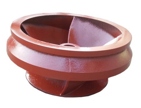
What Is a Mixed Flow Impeller?
A mixed flow impeller has blades shaped to discharge fluid diagonally, usually at an angle between axial and radial flow. This geometry allows the impeller to generate head through both centrifugal action and lift generated by the blade profile. In pump engineering, mixed flow designs are commonly selected when the required duty point falls between axial-flow and radial-flow pump performance ranges.
Typical mixed flow pump applications involve:
- High flow rate with medium head
- Continuous-duty operation
- Large-diameter pump casings or vertical pump columns
- Low to moderate solids content, depending on blade design
- Demand for better efficiency than oversized radial impellers at high flow
Mixed Flow Impeller vs Axial and Radial Impeller
Correct impeller selection affects pump efficiency, motor power, vibration, bearing life and total operating cost. The table below compares the mixed flow impeller with axial and radial alternatives from an engineering and procurement perspective.
| Item | Mixed Flow Impeller | Axial Flow Impeller | Radial Flow Impeller |
|---|---|---|---|
| Flow direction | Diagonal: axial plus radial | Parallel to shaft | Perpendicular to shaft |
| Best application range | High flow, medium head | Very high flow, low head | Lower flow, high head |
| Efficiency advantage | Strong at medium specific speed | Strong at very high specific speed | Strong at low specific speed |
| NPSH behavior | Often favorable with optimized inlet profile | Generally favorable at low head | Can be more sensitive at high speed |
| Solids tolerance | Moderate to good with open or semi-open design | Good for large flow channels | Depends heavily on passage width |
| Typical industries | Irrigation, drainage, cooling water, seawater, wastewater | Flood control, circulation, aquaculture | Boiler feed, process transfer, pressure boosting |
For buyers comparing impeller types, the key point is simple: a mixed flow impeller is often the most practical choice when an axial impeller cannot provide enough head and a radial impeller becomes inefficient or oversized at the required flow rate.
Key Design Features
The hydraulic geometry of a mixed flow impeller is defined by inlet diameter, outlet width, blade inlet angle, blade outlet angle, hub-to-tip ratio, meridional channel profile and blade surface curvature. These parameters determine the pump curve, efficiency, cavitation margin and operating stability.
- Diagonal discharge path: supports both flow capacity and pressure generation.
- Hydraulic blade profile: reduces separation, recirculation and hydraulic loss.
- Optimized leading edge: improves suction performance and reduces cavitation risk.
- Balanced rotating mass: helps reduce vibration and bearing load.
- Custom hub and bore design: supports direct replacement in existing pumps.
- Open, semi-open or enclosed construction: selected according to liquid cleanliness and efficiency targets.
For performance-critical applications, hydraulic matching between the impeller, pump casing, diffuser or volute is essential. Replacing an impeller by diameter alone may not restore original pump performance if the blade angle, passage area or trim geometry differs from the original design.
Available Mixed Impeller Types
Mixed impellers are not one single design. The best configuration depends on the pumped liquid, required head, installation type, efficiency target and maintenance conditions.
Open Mixed Flow Impeller
An open mixed flow impeller has no front shroud and exposes the blade passages. It is suitable for liquids containing suspended solids, fibers or light debris. It is easier to clean and inspect, but it may have lower hydraulic efficiency than enclosed designs and can be more sensitive to wear clearance.
Semi-Open Mixed Flow Impeller
A semi-open design uses one shroud and open blade passages on the opposite side. It provides a compromise between solids handling, manufacturability and efficiency. Semi-open mixed impellers are common in drainage, wastewater and industrial circulation pumps.
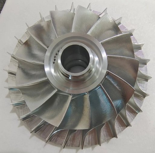
Enclosed Mixed Flow Impeller
An enclosed mixed flow impeller uses front and rear shrouds to guide the fluid through defined passages. It usually provides higher efficiency and better hydraulic control for clean water, cooling water, condensate and seawater transfer applications.
Adjustable or Custom Blade Mixed Flow Impeller
For large vertical pumps or retrofit projects, blade geometry can be customized to match a new duty point. Adjustments may include blade angle correction, outlet diameter trimming, inlet edge modification and passage polishing.
Materials for Mixed Flow Impeller Manufacturing
Material selection should consider corrosion, erosion, temperature, suspended solids, galvanic compatibility, welding repair requirements and lifecycle cost. We manufacture mixed flow impellers in cast, forged or machined materials according to application severity.
| Material | Typical Use | Engineering Advantage |
|---|---|---|
| Ductile iron | General water, irrigation, drainage | Cost-effective strength and good castability |
| Cast steel | Industrial water, higher mechanical load | Higher toughness than grey iron |
| Stainless steel 304 / 316 | Clean water, mildly corrosive fluids, seawater with limits | Improved corrosion resistance and clean surface finish |
| Duplex stainless steel | Seawater, brine, corrosive industrial liquid | High strength and chloride corrosion resistance |
| Bronze / aluminum bronze | Marine water, cooling systems, vertical pumps | Good corrosion resistance and anti-galling behavior |
| Wear-resistant alloys | Sandy water, slurry-like service, abrasive flow | Improved erosion resistance at leading edges and passages |
For seawater, reclaimed water or abrasive service, material compatibility is more important than initial purchase price. A lower-cost material may fail early if chloride pitting, sand erosion or cavitation damage is not considered during selection.
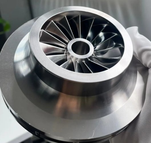
Manufacturing and Machining Capability
Mixed flow impellers require accurate geometry because small deviations in blade profile, inlet edge and dynamic balance can change the pump curve. Our manufacturing process can include pattern making, casting simulation, precision casting, CNC machining, five-axis blade surface machining, bore machining, keyway cutting, heat treatment, non-destructive testing and dynamic balancing.
- Reverse engineering from worn or broken impeller samples
- 3D scanning and CAD reconstruction of blade surfaces
- Hydraulic profile correction based on duty point requirements
- CNC turning of hub, wear ring seat, bore and shroud surfaces
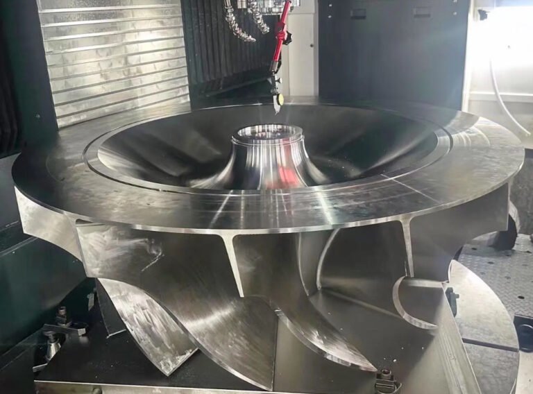
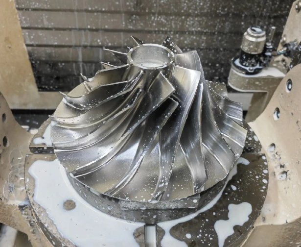
- Five-axis milling for complex blade and passage geometry
- Static and dynamic balancing according to project requirements
- Surface finishing, polishing, coating or passivation when specified
Typical inspection items include outer diameter, inlet diameter, blade count, blade thickness, bore tolerance, keyway width, hub runout, shroud runout, surface roughness, balance grade and material certificate verification.
Machining tolerances commonly reviewed by pump engineers
Common control points include impeller bore fit, shaft shoulder contact, keyway alignment, wear ring concentricity, axial face runout and dynamic balance. Final tolerances depend on pump size, rotational speed, shaft design and applicable project standard.
Engineering Performance and Selection Data
A mixed flow impeller should be selected by operating duty, not only by size. Important data include flow rate, head, rotational speed, liquid density, viscosity, vapor pressure, suction condition, available NPSH, motor power, installation type and allowable vibration.
| Parameter | Why It Matters | Typical Engineering Check |
|---|---|---|
| Flow rate | Determines passage area and blade loading | Rated, minimum and maximum operating flow |
| Total head | Defines energy rise required from the impeller | Static head plus friction loss |
| Speed | Affects head, efficiency, NPSH and stress | rpm, variable frequency drive range |
| NPSH available | Controls cavitation risk | NPSHa should exceed NPSHr with margin |
| Liquid condition | Influences material and blade passage design | Temperature, solids, corrosion, viscosity |
| Balance and vibration | Protects shaft, bearings and seals | Balance grade and operating vibration limit |
In one retrofit example for a cooling water circulation pump, the original impeller operated far to the right of its best efficiency point. After redesigning the outlet width and blade discharge angle, the pump returned closer to the specified duty point. The measured result showed approximately 6% lower absorbed power at the same flow rate and reduced bearing housing vibration from 4.8 mm/s to 2.9 mm/s RMS. Actual results vary by pump casing, installation condition and test accuracy, but this illustrates why impeller geometry should be engineered rather than copied only by diameter.
Common Engineering Problems Solved by a Mixed Flow Impeller
A correctly designed mixed impeller can solve several practical pump problems that appear in high-flow systems. These issues are often reported by maintenance teams after pump repair, duty change or pipeline modification.
- Insufficient flow: caused by wrong impeller trim, blocked passages, incorrect blade angle or poor hydraulic matching.
- Excessive vibration: caused by imbalance, cavitation, recirculation, bent shaft, uneven wear or poor casting quality.
- High energy consumption: caused by operation away from best efficiency point or oversized pump selection.
- Cavitation damage: caused by low NPSH margin, sharp inlet edge, suction turbulence or excessive speed.
- Rapid erosion: caused by sandy water, high local velocity, unsuitable alloy or poor surface finish.
- Premature bearing wear: caused by hydraulic radial load, imbalance or unstable operation at low flow.
For critical services, root-cause analysis should be completed before ordering a replacement impeller. If the failure mode is cavitation, corrosion or hydraulic mismatch, replacing the same geometry may repeat the same failure.
Information needed for replacement or retrofit evaluation
- Pump model, serial number and installation orientation
- Existing impeller drawing, sample or 3D scan data
- Required flow rate, head and speed
- Motor power and frequency control range
- Liquid name, temperature, solids and corrosion level
- Photos of damaged areas, wear rings, casing and shaft fit
- Current vibration, noise, cavitation or performance symptoms
Quality Control and Testing
Quality control for a mixed flow impeller must verify both mechanical integrity and hydraulic accuracy. A visually acceptable casting may still cause low efficiency or high vibration if the blade profile, mass distribution or impeller machining datum is incorrect.
- Material certificate and chemical composition verification
- Dimensional inspection against drawing or 3D model
- Dye penetrant, magnetic particle or ultrasonic testing when required
- Hardness testing for wear-resistant or heat-treated alloys
- Dynamic balancing for rotating stability
- Surface roughness inspection for hydraulic passages
- Final fit check for bore, keyway, hub and wear ring seat
For pump acceptance testing, standards such as ISO 9906 can be used to evaluate hydraulic performance where applicable. For petrochemical or heavy-duty pump projects, requirements may also be aligned with project specifications based on API 610 principles, although the exact standard depends on the pump type and end-user contract.
Buyer and Engineer Selection Checklist
Procurement teams often compare price, delivery time and material, while engineers focus on duty point, hydraulic reliability and mechanical fit. A successful mixed flow impeller purchase should satisfy both perspectives.
| Checklist Item | Buyer Concern | Engineer Concern |
|---|---|---|
| Material grade | Cost and availability | Corrosion, erosion and strength |
| Drawing accuracy | Clear quotation scope | Correct hydraulic and mechanical fit |
| Machining process | Lead time and repeatability | Runout, bore tolerance and balance |
| Inspection documents | Traceability and acceptance | Dimensional, material and NDT compliance |
| Performance target | Operating cost impact | Efficiency, NPSH and vibration margin |
The most reliable specification includes a drawing or sample, operating duty point, liquid data and failure history. This enables the manufacturer to decide whether a direct replacement, material upgrade or hydraulic redesign is the better solution.
Why the lowest impeller price may increase lifecycle cost
A low-cost impeller can become expensive if it has poor balance, rough blade passages, incorrect alloy or inaccurate hydraulic geometry. The result may be higher power consumption, repeated maintenance, seal damage, bearing failure or production downtime.
Typical Applications
Mixed flow impellers are used in systems where large flow capacity and stable medium-head performance are required. Common application areas include:
- Irrigation and agricultural pumping stations
- Municipal drainage and flood control pumps
- Power plant cooling water circulation
- Seawater intake and desalination support systems
- Industrial process water transfer
- Wastewater and reclaimed water pumping
- Marine ballast and dock pumping systems
- Mining water management and dewatering
- Large HVAC and district cooling circulation
For these services, stable hydraulic performance is often more valuable than maximum peak efficiency alone. A well-designed mixed flow impeller should operate reliably across the expected flow range without excessive vibration, cavitation or overload.
Specification Options
Mixed flow impellers can be manufactured according to customer drawings, reverse-engineered from a sample, or redesigned for a new pump duty. The following options are commonly specified:
- Impeller type: open, semi-open or enclosed
- Blade count and blade profile
- Outer diameter and trimming diameter
- Hub bore, keyway, taper or spline connection
- Wear ring seat and sealing clearance design
- Material grade and heat treatment
- Surface coating, polishing or passivation
- Dynamic balancing grade
- Inspection level and documentation package
- Packing method for export or long-term storage
Summary
A mixed flow impeller is the preferred solution for many high-flow, medium-head pump systems because it combines axial flow capacity with radial pressure generation. Compared with axial and radial impellers, it often provides a better operating balance for irrigation, drainage, cooling water, seawater transfer and industrial circulation.
For a reliable Mixed Impeller project, selection should be based on hydraulic duty, pump casing compatibility, NPSH margin, material suitability, machining accuracy and balance quality. With proper engineering and manufacturing control, a mixed flow impeller can reduce energy consumption, improve pump stability and extend maintenance intervals in demanding fluid transfer applications.