Centrifugal Impellers are rotating flow components designed to convert mechanical shaft power into velocity and pressure by accelerating fluid or gas radially outward from the impeller eye to the outlet. They are widely used in centrifugal pumps, industrial fans, turbo blowers, compressors, HVAC systems, wastewater equipment, chemical processing units, marine systems and power-generation auxiliaries.
This product page is written for engineers, sourcing teams and equipment builders who need to compare impeller types, confirm materials, evaluate manufacturing routes and reduce field risks such as vibration, cavitation, erosion, low efficiency or premature bearing failure.
Product Overview: What a Centrifugal Impeller Does
A centrifugal impeller typically consists of an inlet eye, hub, blades or vanes, front and rear shrouds, outlet diameter and sometimes wear-ring seats or balance holes. When the impeller rotates, fluid enters axially or near-axially, gains kinetic energy through the blade passages and exits radially into a volute casing or diffuser where velocity is partly converted into pressure.
In pump applications, impeller geometry affects head, flow rate, NPSH requirement, cavitation margin and hydraulic efficiency. In fan and blower applications, blade angle, inlet cone alignment, tip clearance and dynamic balance strongly influence airflow, static pressure, sound level and motor load.
- Typical applications: water pumps, slurry pumps, chemical pumps, industrial ventilation, dust collection, combustion air, wastewater aeration and marine cooling.
- Common flow media: clean water, seawater, wastewater, oil, chemicals, air, flue gas, steam condensate, abrasive slurry and corrosive fluids.
- Key design terms: impeller eye, blade outlet angle, specific speed, best efficiency point, shroud clearance, wear ring clearance, tip speed and shaft fit.
Types of Centrifugal Impellers
Different impeller constructions are selected according to flow condition, solids content, efficiency target, maintenance access and manufacturing cost. The correct selection reduces total lifecycle cost more effectively than choosing only by purchase price.
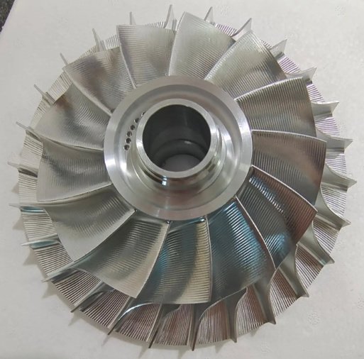
Closed Centrifugal Impellers
Closed impellers have front and rear shrouds that enclose the blade passages. They are commonly used in clean-water pumps and process pumps where high efficiency and stable hydraulic performance are required. They usually require controlled wear-ring clearance to maintain performance.
Semi-Open Centrifugal Impellers
Semi-open impellers have one shroud and exposed blade passages on the other side. They are suitable for fluids containing small solids or fibers, and they allow easier inspection and cleaning compared with closed impellers.
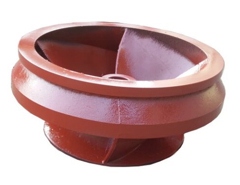
Open Centrifugal Impellers
Open impellers have exposed blades without front and rear shrouds. They are often used for viscous fluids, slurry, wastewater or applications where clogging resistance is more important than peak efficiency.
Backward-Curved, Radial and Forward-Curved Impellers
For fans and blowers, blade curvature determines pressure generation, efficiency and power behavior. Backward-curved impellers are preferred for high efficiency and non-overloading power characteristics, radial-blade impellers are robust for dust-laden gas, and forward-curved impellers are compact but typically used at lower pressures.
| Impeller Type | Best Fit | Advantages | Limitations |
|---|---|---|---|
| Closed impeller | Clean liquids, process pumps, high-efficiency service | High hydraulic efficiency, stable head-flow curve | More sensitive to clogging and wear-ring clearance |
| Semi-open impeller | Light solids, viscous fluids, general industrial pumping | Better clogging resistance, easier inspection | Efficiency depends on axial clearance control |
| Open impeller | Wastewater, slurry, fibrous media | Good solids handling, easier cleaning | Lower efficiency and higher wear risk |
| Backward-curved impeller | Industrial fans and blowers | High efficiency, stable power curve | Requires accurate blade forming and balancing |
| Radial-blade impeller | Dust collection, material handling gas streams | Strong blade structure, erosion tolerant | Usually noisier and less efficient than backward-curved designs |
Performance Parameters Engineers Usually Specify
A centrifugal impeller should not be specified by diameter alone. Reliable selection requires matching the impeller with the casing, shaft speed, operating point and fluid properties. A small change in blade outlet width, inlet eye diameter or trimming diameter can noticeably change flow, head and power consumption.
- Flow rate: m³/h, L/s, GPM, CFM or other project units.
- Head or pressure rise: meters, kPa, Pa, bar, mmAq or in.wg.
- Rotational speed: RPM and drive type, including direct drive, belt drive or variable frequency drive.
- Fluid or gas properties: density, viscosity, temperature, vapor pressure, solids content and corrosiveness.
- Hydraulic or aerodynamic target: efficiency, noise level, cavitation margin and operating range.
- Mechanical constraints: shaft bore, keyway, taper lock, hub length, maximum outer diameter and casing clearance.
Engineering note: impeller trimming and affinity laws
Impeller trimming is often used to reduce pump head or flow without changing the casing. As a simplified rule for geometrically similar conditions, flow is roughly proportional to impeller diameter, head is proportional to diameter squared, and power is proportional to diameter cubed. Actual results must be verified because blade outlet width, vane angle, casing geometry and efficiency loss after trimming can change the curve.
Material Options for Centrifugal Impellers
Material selection depends on corrosion, erosion, temperature, fatigue load, weldability, hygiene requirements and cost. For rotating components, strength and balance stability are as important as corrosion resistance.
| Material | Typical Use | Key Benefit |
|---|---|---|
| Cast iron / ductile iron | Water pumps, HVAC, general industrial service | Cost-effective, good castability and damping |
| Carbon steel | Blowers, heavy-duty fans, moderate-temperature systems | High strength and good weldability |
| 304 / 316 stainless steel | Chemical, food, marine and corrosive environments | Corrosion resistance and clean surface finish |
| Duplex stainless steel | Seawater, chloride service, high-strength applications | Better pitting resistance and higher mechanical strength |
| Bronze | Marine pumps, seawater cooling, non-sparking applications | Good seawater resistance and anti-galling properties |
| Aluminum alloy | Lightweight fans, high-speed air movement | Low mass and reduced rotating inertia |
| Wear-resistant alloys or hardfacing | Slurry, ash, sand and abrasive media | Improved erosion life in severe service |
For corrosive or abrasive service, coating systems such as epoxy coating, rubber lining, ceramic coating, tungsten carbide coating or hardfacing can be considered. Coating thickness should be included in clearance calculations to avoid unexpected rubbing or efficiency loss.
Manufacturing and Machining Capabilities
Impellers can be manufactured by casting, forging, fabrication, welding, precision machining, additive-assisted methods or a combination of these processes. The best route depends on volume, material, impeller diameter, blade complexity and required repeatability.
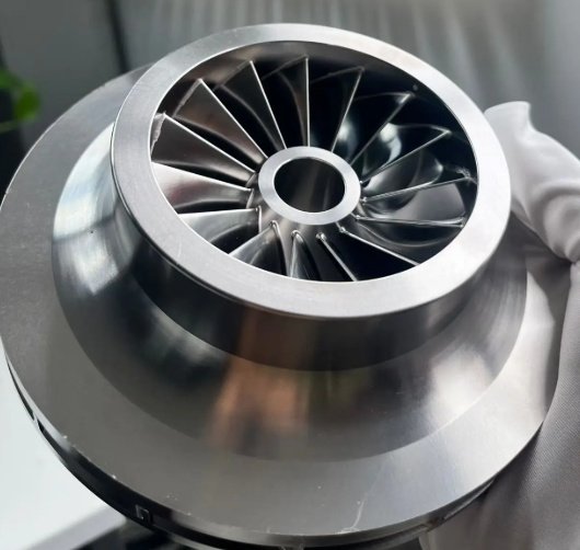
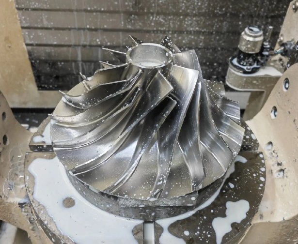
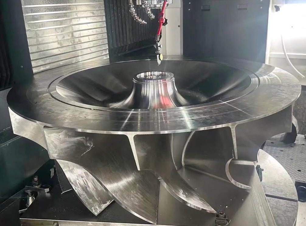
5-axis CNC machining is suitable for complex blade profiles, small-to-medium batch custom impellers, prototypes, compressor wheels and applications requiring tight dimensional control. CNC machining can achieve consistent blade thickness, accurate hub geometry, smooth passage transitions and repeatable shaft fits.
Casting is cost-effective for medium and large production volumes, especially for pump impellers with repeatable geometry. After casting, critical surfaces such as bore, hub face, wear-ring seats, rear balancing surfaces and mounting faces are machined to drawing requirements.
Fabricated and welded impellers are commonly used in industrial fans, large blowers and heavy-duty air-handling systems. Blade positioning, weld sequence and stress relief are important to control distortion before final balancing.
- CNC operations: turning, milling, 5-axis blade machining, bore finishing, keyway cutting and thread machining.
- Post-processes: heat treatment, stress relieving, shot blasting, passivation, polishing, coating and hardfacing.
- Inspection: CMM measurement, runout check, surface roughness inspection, dye penetrant testing, ultrasonic testing and material certification.
- Balancing: static balancing and dynamic balancing according to project speed and vibration limits.
Manufacturing note: cast versus CNC-machined impellers
Cast impellers usually provide lower unit cost at higher quantities, while CNC-machined impellers reduce tooling cost and shorten development cycles for prototypes or replacement parts. For reverse-engineered impellers, CNC machining from billet or from a near-net casting can be useful when original patterns are unavailable.
Comparison: Centrifugal Impellers vs Axial and Mixed-Flow Impellers
The search for an impeller often starts with uncertainty about flow direction. Centrifugal, axial and mixed-flow impellers are not interchangeable in most equipment because they are designed for different pressure-flow characteristics.
| Feature | Centrifugal Impeller | Axial Impeller | Mixed-Flow Impeller |
|---|---|---|---|
| Flow direction | Fluid enters near the axis and exits radially | Fluid moves mainly parallel to the shaft | Fluid exits at an angle between axial and radial |
| Pressure capability | Medium to high pressure or head | Low pressure, high flow | Medium flow and medium head |
| Typical equipment | Centrifugal pumps, blowers, radial fans | Cooling fans, propeller pumps, ventilation | Drainage pumps, circulation pumps, large flow systems |
| Efficiency sensitivity | Sensitive to casing match, clearance and blade shape | Sensitive to tip clearance and blade pitch | Sensitive to both casing and blade outlet angle |
| Best selection case | When pressure rise is more important than maximum free flow | When large volume flow at low pressure is required | When both flow and head are moderate |
Real Engineering Problems and Measurable Improvements
Many impeller replacement projects are not simple spare-part purchases. They are driven by vibration alarms, reduced flow, energy waste, corrosion, cavitation damage or short service life. In these cases, dimensional accuracy, material selection and balancing quality can produce measurable results.
Case Example 1: Fan Vibration Reduction
A welded carbon-steel backward-curved fan impeller operating at 2,950 RPM showed excessive vibration after blade repair. The root cause was uneven weld build-up and accumulated imbalance. After machining the hub faces, correcting blade deposits and applying two-plane dynamic balancing to ISO 1940 grade G2.5, measured bearing housing vibration was reduced from approximately 7.8 mm/s RMS to 2.1 mm/s RMS under comparable operating conditions.
Case Example 2: Pump Efficiency Recovery
A closed stainless steel pump impeller used in a chemical transfer pump had worn wear-ring seats and eroded blade outlet edges. Replacing the impeller and restoring the wear-ring clearance from about 0.85 mm to 0.30 mm helped recover approximately 6% to 9% flow at the same speed, based on site flowmeter readings and motor current comparison.
Case Example 3: Slurry Service Life Extension
For a slurry pump handling sand-containing process water, the original cast iron open impeller showed severe leading-edge erosion within three months. Changing to a high-chromium wear-resistant alloy and increasing leading-edge thickness extended observed service life to more than seven months in the same duty cycle.
These examples show why the lowest-cost impeller is not always the lowest-cost operating choice. When downtime, motor load, bearing life and replacement frequency are included, optimized impeller manufacturing can deliver a stronger economic result.
Dimensional Specifications and Customization Data
Custom Centrifugal Impellers can be produced from drawings, 3D models, samples or performance requirements. For accurate production and interchangeability, the following information is normally required.
| Specification Item | Engineering Importance | Typical Data Required |
|---|---|---|
| Outer diameter | Controls head, tip speed and casing clearance | Finished OD, trim diameter, tolerance |
| Inlet eye diameter | Affects inlet velocity and cavitation risk | Eye ID, inlet radius, suction side geometry |
| Blade geometry | Determines flow, pressure and efficiency | Blade count, thickness, inlet angle, outlet angle |
| Hub and bore | Ensures shaft fit and torque transmission | Bore size, H7 or project tolerance, keyway, taper, thread |
| Shrouds and wear rings | Controls leakage and rubbing risk | Ring diameter, width, axial clearance, material pairing |
| Surface finish | Influences friction loss and fouling tendency | Ra value, polishing direction, coating requirement |
| Balancing grade | Reduces vibration and bearing load | ISO 1940 G6.3, G2.5, G1.0 or project-specific requirement |
Reverse engineering note for replacement impellers
When original drawings are unavailable, an existing impeller can be measured by 3D scanning, CMM inspection and manual verification of critical fits. However, worn parts should not be copied blindly. Wear-ring surfaces, blade tips, inlet edges and corrosion-damaged areas should be corrected using casing dimensions and operating data.
Quality Control and Documentation
Impellers are rotating components, so inspection should cover both geometry and mechanical integrity. A typical quality package may include dimensional reports, material certificates, balancing reports and non-destructive testing records.
- Material traceability: EN 10204 3.1 certificate, chemical composition and mechanical properties where applicable.
- Dimensional inspection: bore, keyway, runout, OD, wear-ring seat, hub face and blade passage checks.
- Dynamic balancing: single-plane or two-plane balancing based on rotor width, speed and service criticality.
- Non-destructive testing: dye penetrant testing for stainless steel and non-ferrous parts, magnetic particle testing for ferromagnetic parts, ultrasonic testing for heavy sections.
- Surface inspection: roughness measurement, coating thickness, passivation quality and visual defect checking.
- Packing control: shaft bore protection, corrosion prevention, anti-impact packaging and orientation marking.
For high-speed impellers, overspeed testing, finite element analysis, modal review and rotor dynamics evaluation may be required. These checks help prevent failures caused by excessive centrifugal stress, resonance or inadequate hub strength.
Procurement Guidance for Buyers and Engineers
A well-prepared impeller inquiry reduces engineering clarification time and prevents costly remanufacturing. Buyers should evaluate not only unit price, but also drawing control, process capability, inspection scope, balancing method and experience with similar media.
- Confirm whether the impeller is for a pump, fan, blower or compressor-related assembly.
- Provide the operating speed, motor power, flow rate, head or pressure, and working temperature.
- Identify the medium, including corrosive chemicals, chloride content, solids size, solids concentration or gas dust loading.
- Define the required material standard, heat treatment, coating and surface finish.
- Specify the balancing grade and whether balancing should be performed with coupling, sleeve, wear rings or other rotating accessories.
- Check interchangeability with the casing, shaft, wear rings, seals and inlet cone before approving production.
- For replacement parts, compare the old impeller’s actual wear with the original hydraulic or aerodynamic design intent.
The most reliable Centrifugal Impellers are produced when hydraulic design, material engineering, precision machining and rotor balancing are treated as one integrated manufacturing process. This approach improves efficiency, reduces vibration and supports longer service life in demanding industrial equipment.