
Carbon Steel Machining Services
- Fast prototype & low MOQ support
- Tight tolerance up to +0.002mm
- Surface finishing available
- Engineering review before production
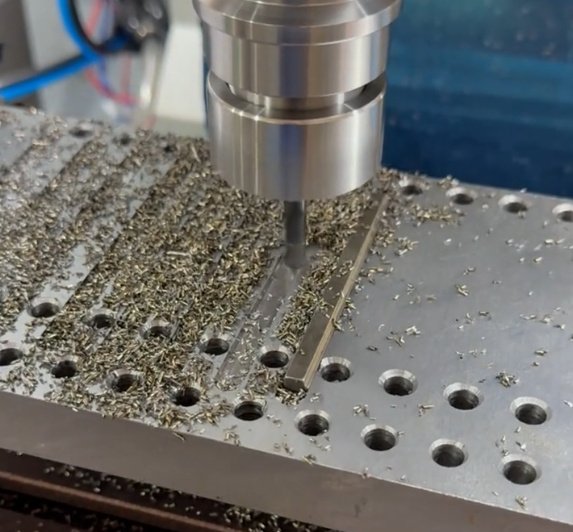
Carbon Steel CNC Machining Capabilities
Precision Milling
- Multi-axis CNC milling for complex geometries.
- Tight tolerances as tight as ±0.002mm and fine surface finishes.
- Suitable for prototypes and mass production.
CNC Turning
- High-speed turning for shafts, rods, and cylindrical parts.
- Thread cutting, grooving, and facing operations.
- Supports both small and large batch production.
Drilling, Tapping & Boring
- CNC drilling for holes of all sizes and depths.
- Threading and tapping for assemblies.
- High repeatability for precision alignment.
Multi-Axis Machining
- 4-axis and 5-axis machining for intricate parts.
- Reduced setups and improved accuracy.
- Ideal for aerospace, automotive, and medical components.
Secondary Operations
- Deburring, grinding, tapping, honing, keyways, broaching support.
- Specialized processes for hard-to-machine metals.
- Used when critical surfaces, fit, or assembly requirements exceed standard machining
CNC Prototyping
- Rapid CNC prototyping to test designs quickly.
- Small batch to full-scale production runs.
- Flexible workflow to meet tight deadlines.
Surface Finishing and Post-Processing Options
Carbon steel is strong and economical, but it can corrode if left unprotected. Machined carbon steel parts often require surface finishing based on operating environment, cosmetic requirements, friction, wear, and assembly function.
- Black oxide: Common for mild corrosion resistance and dark appearance with minimal dimensional change.
- Zinc plating: Provides improved corrosion protection for brackets, fasteners, and mechanical components.
- Phosphate coating: Used for wear-in, oil retention, and corrosion resistance in industrial applications.
- Painting or powder coating: Suitable for large carbon steel parts, frames, covers, and exposed equipment components.
- Heat treatment: Can improve hardness, strength, and wear resistance for medium or high carbon steels.
- Grinding: Used when tighter size control, roundness, or surface finish is required after CNC machining.
- Protective oil: Short-term rust prevention for parts shipped or stored before assembly.
Carbon Steel Grades We Machine
| Material Grade | Type | Machining Characteristics | Common Uses |
|---|---|---|---|
| AISI 1018 | Low carbon steel | Good machinability, weldability, and dimensional control | Shafts, pins, spacers, mounting blocks, fixtures |
| AISI 1020 | Low carbon steel | Balanced strength and machinability; suitable for general-purpose parts | Brackets, structural parts, plates, couplings |
| AISI 1045 | Medium carbon steel | Higher strength; may require more controlled feeds and tool selection | Gears, shafts, rollers, machine components |
| AISI 1050 / 1060 | Medium to high carbon steel | Higher hardness potential; heat treatment planning is important | Wear plates, blades, mechanical drive parts |
| A36 | Structural carbon steel | Cost-effective and available in plates and shapes; variable machinability by lot | Base plates, frames, weldments, large machined structures |
| 12L14 / 1215 | Free-machining carbon steel | Excellent chip breaking and high productivity; limited weldability for some grades | High-volume turned parts, fittings, fasteners, inserts |
Material selection notes for carbon steel machined parts
For parts requiring weldability and moderate strength, 1018, 1020, and A36 are common choices. For shafts, rollers, and mechanical transmission parts that require higher strength or wear resistance, 1045 and 1050 may be preferred. For high-volume screw-machined components, 12L14 or 1215 can reduce cycle time and tool wear, but application limits such as weldability, lead content, and regulatory requirements should be reviewed before selection.
Precision CNC Machined Carbon Steel Parts
Precision carbon steel machining requires more than cutting metal to shape. It involves material condition control, fixturing, cutter geometry, cutting heat management, inspection planning, and understanding how carbon steel responds to internal stress. For tight-tolerance carbon steel components, we evaluate part geometry and critical dimensions before production begins.
Typical achievable tolerances depend on material, part size, geometry, and inspection method. As a practical machining reference, many carbon steel parts can be produced to general CNC tolerances around ±0.005 in or ±0.13 mm. Precision features may be held tighter, such as ±0.001 in or ±0.025 mm, when the part design, setup, machine condition, and inspection environment support it.
| Feature Type | Typical Machining Target | Factors That Affect Results |
|---|---|---|
| Turned outside diameter | ±0.001 to ±0.003 in | Length-to-diameter ratio, material hardness, tool wear, live center support |
| Bored inside diameter | ±0.0015 to ±0.005 in | Bore depth, tool deflection, chip evacuation, finish requirement |
| Milled flatness | Application-dependent | Part size, residual stress, stock removal balance, clamping pressure |
| Hole position | Per drawing GD&T | Datum strategy, setup count, fixture repeatability, inspection equipment |
| Threaded features | Class fit per specification | Thread form, tapping depth, lubrication, heat treatment condition |
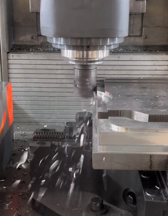
Large Carbon Steel Machined Parts
Large carbon steel machined parts require a different process strategy than small precision parts. Size, weight, stress relief, stock condition, and handling method all affect final accuracy. In large plates, weldments, frames, and bases, dimensional movement can occur after roughing because internal stresses are released as material is removed.
For large carbon steel machined parts, the machining plan may include rough machining, stress-relief treatment, semi-finishing, rest periods, and final finishing. This approach improves flatness, hole alignment, bearing surface quality, and repeatability across production lots.
Typical Large-Part Engineering Controls
- Balanced material removal from opposite faces to reduce warping
- Purpose-built fixtures to prevent clamping distortion
- Datum machining strategy for repeatable inspection and assembly
- Roughing and finishing separation when high flatness or parallelism is required
- Crane, forklift, and lifting-point planning for safe handling of heavy components
- Inspection using height gauges, CMM, laser measurement, bore gauges, and surface plates when applicable
Carbon Steel CNC Machining Process
A stable process for carbon steel cnc machining starts with manufacturability review and ends with documented inspection. The actual process may vary based on the part, but the following workflow is common for production-quality components.
- Drawing and CAD review: Check dimensions, tolerances, datum structure, surface finishes, threads, edge breaks, and notes.
- Material confirmation: Verify grade, condition, bar or plate form, certification needs, and heat treatment requirements.
- Process planning: Select turning, milling, drilling, boring, grinding, or combined operations.
- Fixturing and workholding: Design setups that control vibration, deflection, and positional accuracy.
- Rough machining: Remove bulk material while controlling heat, chip load, and stress release.
- Semi-finishing and finishing: Machine critical features after the part is stable.
- Deburring and edge control: Remove sharp edges and burrs that can affect assembly or safety.
- Inspection: Verify critical-to-quality dimensions, GD&T callouts, threads, bores, and surface finish.
- Finishing or protection: Apply black oxide, phosphate, zinc plating, oiling, painting, or other corrosion-control methods when specified.
DFM considerations before machining carbon steel
Carbon steel designs are easier to machine when deep pockets include generous corner radii, thin walls are supported, hole depths are realistic, and tolerances are applied only where function requires them. A tolerance such as ±0.0005 in on a non-critical face can increase cost significantly, while the same tolerance on a bearing fit may be fully justified. Early DFM review helps reduce machining time, scrap risk, and inspection complexity.
CNC Carbon Steel Machining Challenges and Solutions
| Engineering Issue | Why It Happens | Machining Solution |
|---|---|---|
| Long chips in low carbon steel | Ductile material behavior and insufficient chip breaking | Use chip-breaker inserts, optimized feed rate, coolant, and interrupted tool paths when needed |
| Part distortion after roughing | Residual stress release in bar, plate, or flame-cut stock | Use stress relief, rough/semi-finish/final process, and balanced machining |
| Poor surface finish | Built-up edge, vibration, tool wear, or unstable fixturing | Adjust speed, feed, insert grade, nose radius, coolant flow, and workholding rigidity |
| Thread quality variation | Tool wear, chip packing, misalignment, or hard material condition | Use thread milling, forming or cutting taps as appropriate, and thread gauges for verification |
| Hole straightness problems | Deep drilling deflection and poor chip evacuation | Use pilot holes, peck cycles, gun drilling support, boring, or reaming based on tolerance |
Example: Improving Repeatability on a Carbon Steel Shaft
| Measured Item | Before Process Review | After Process Review |
|---|---|---|
| Diameter variation across batch | Up to 0.004 in | Within 0.0015 in |
| Runout at critical diameter | 0.003 to 0.005 in | Typically below 0.002 in |
| Rework rate | Approximately 8% | Below 2% |
| Primary improvement | Reactive correction | Controlled datum-based machining plan |
Quality Control for Carbon Steel Machined Components
Typical inspection documentation available for carbon steel parts
Inspection documentation may include first article inspection, dimensional reports, material certificates, heat treatment certificates, plating or coating certificates, hardness readings, thread gauge results, and production inspection records. Documentation level should be defined before production to avoid delays and ensure the part meets purchasing and engineering requirements.
Industries and Applications
- Industrial machinery: mounting plates, housings, guides, rollers, shafts, machine bases
- Automotive and transportation: brackets, bushings, spacers, pins, linkage parts, drivetrain components
- Energy and power equipment: flanges, couplings, supports, valve-related components, heavy-duty hardware
- Construction and lifting equipment: structural plates, pins, blocks, weldment-machined parts
- Tooling and fixtures: jigs, nests, clamps, locating blocks, inspection fixtures
- Agricultural equipment: shafts, hubs, brackets, wear components, pivot parts
Why Carbon Steel Is Often Chosen for CNC Machining
| Selection Factor | Carbon Steel Advantage | Design Consideration |
|---|---|---|
| Cost | Generally economical for both prototypes and production | Finishing may be required for corrosion protection |
| Strength | Good mechanical performance, especially in medium carbon grades | Heat treatment may affect distortion and final machining sequence |
| Machinability | Many grades machine efficiently with proper tooling | Grade selection strongly affects chip control and tool life |
| Availability | Commonly stocked in many shapes and sizes | Large plates and flame-cut stock may contain residual stress |
| Finish options | Compatible with plating, coating, black oxide, phosphate, and painting | Finish thickness and masking requirements should be specified early |
Design Information Needed for Accurate Carbon Steel Machining
- 2D drawing with tolerances, datum references, GD&T, threads, and surface finish callouts
- 3D CAD file such as STEP, IGES, Parasolid, or native CAD format
- Carbon steel grade and material condition, such as hot rolled, cold drawn, normalized, or heat treated
- Required quantity, delivery schedule, and batch release plan
- Surface treatment, corrosion protection, masking, or post-machining coating requirements
- Inspection level, first article needs, material certification, and critical-to-function dimensions
- Packaging requirements to protect machined surfaces and prevent rust during shipment