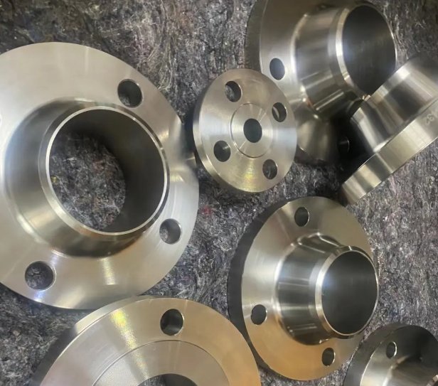
Copper Nickel Flanges are corrosion-resistant pipe connection components used in seawater cooling, ballast, firewater, desalination, shipbuilding, offshore platforms and coastal industrial piping. Manufactured mainly from CuNi 90/10 and CuNi 70/30 alloys, these flanges combine reliable resistance to chloride-bearing water with good machinability, weldability and long service life in demanding marine environments.
This product page is written for engineers, buyers and project procurement teams that need to compare copper nickel flange grades, standards, pressure classes, machining requirements and inspection documentation before placing a technical order.
- Common materials: UNS C70600, UNS C71500, CuNi10Fe1Mn, CuNi30Mn1Fe
- Common types: weld neck, slip-on, blind, socket weld, threaded, lap joint and loose backing flanges
- Dimensional standards: ASME B16.5, ASME B16.47, EN 1092-3, DIN marine flange standards and project drawings
- Applications: seawater intake, condenser cooling, bilge, ballast, brine, fire main, hydraulic return and desalination systems
- Available finishing: raised face, flat face, ring-type joint options where applicable, serrated gasket face and custom drilled bolt patterns
Product Overview: What Are Copper Nickel Flanges?
Copper nickel flanges are mechanical pipe connectors made from copper-nickel alloys containing nickel, iron and manganese. The nickel improves strength and general corrosion resistance, while iron and manganese help stabilize the corrosion film and improve resistance to seawater flow. In seawater piping, copper nickel is often selected because it resists uniform corrosion, macrofouling and chloride attack better than many unprotected ferrous materials.
The most widely used grades are UNS C70600 (90/10) and UNS C71500 (70/30). The 90/10 grade is widely used in shipbuilding and general seawater service because it offers a balanced cost-performance ratio. The 70/30 grade contains higher nickel and is preferred where higher flow velocity, polluted seawater, higher strength or more severe operating conditions are expected.
Material Grades and Alloy Selection
Grade selection should be based on seawater velocity, temperature, oxygen level, risk of sulfide pollution, mechanical load and compatibility with connected pipe, valves and fittings.
| Grade | Common Name | Typical Composition | Typical Use | Engineering Note |
|---|---|---|---|---|
| UNS C70600 | CuNi 90/10 | Approx. 90% Cu, 10% Ni with Fe and Mn | Ship seawater cooling, ballast, bilge, firewater, desalination intake | Commonly selected for standard marine seawater systems where velocity and sulfide levels are controlled. |
| UNS C71500 | CuNi 70/30 | Approx. 70% Cu, 30% Ni with Fe and Mn | Higher velocity seawater, offshore platforms, condensers, severe brine service | Offers higher strength and improved resistance in more aggressive seawater conditions. |
| CW352H / CuNi10Fe1Mn | European 90/10 CuNi | Copper-nickel-iron-manganese alloy | European marine and offshore piping projects | Often specified with EN, DIN or project-based marine standards. |
| CuNi30Mn1Fe | European 70/30 CuNi | Copper-nickel alloy with higher nickel content | High-duty seawater and offshore applications | Used when the project specification requires greater corrosion margin or strength. |
For mixed-material systems, engineers should also review galvanic compatibility. Copper nickel is normally paired with copper nickel pipe, bronze valves, compatible nickel-copper alloys or properly isolated stainless steel components depending on the design.
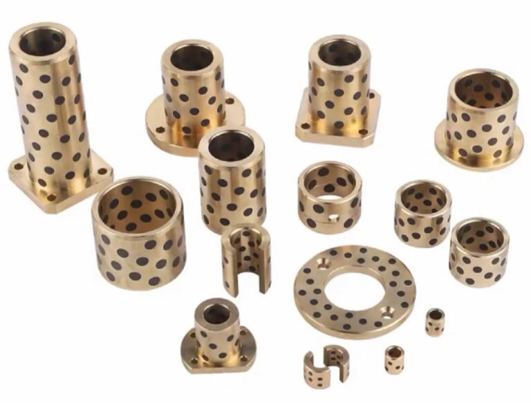
Copper Nickel Flange Types Available
Copper Nickel Flanges are supplied in several configurations to match pipe layout, welding method, pressure rating and maintenance requirements.
| Flange Type | Typical Application | Key Benefit |
|---|---|---|
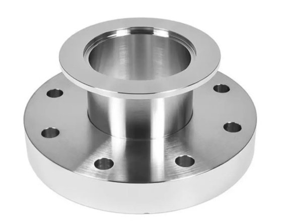
| Weld Neck Flange | High-integrity seawater lines, pump discharge, offshore modules | Long tapered hub improves stress distribution and supports radiographic weld inspection. |
| Slip-On Flange | Low to medium pressure marine piping | Easy alignment and economical installation. |
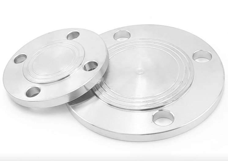
| Blind Flange | Line isolation, test points, system expansion allowance | Provides removable closure for inspection and hydrostatic testing. |
| Lap Joint Flange | Systems requiring frequent dismantling or alignment flexibility | Works with stub ends and allows bolt-hole rotation. |
| Socket Weld Flange | Small-bore CuNi piping | Compact connection with controlled socket depth. |
| Threaded Flange | Special low-pressure maintenance or temporary connections | Used where welding is restricted, subject to engineering approval. |
| Loose Backing Flange | Marine piping with copper nickel collars or stub ends | Reduces copper nickel material cost while retaining corrosion-resistant wetted parts. |
Standards, Sizes and Pressure Classes
Copper nickel flanges can be manufactured to international standards or to project-specific drawings. The dimensional standard defines outside diameter, bolt circle, bolt holes, thickness, hub dimensions and facing, while the material standard defines chemistry, mechanical properties and inspection requirements.
| Item | Available Range or Standard | Notes for Buyers |
|---|---|---|
| Nominal Size | DN15 to DN1200 / 1/2 in. to 48 in. and larger by drawing | Large diameters are commonly supplied as fabricated or machined plate flanges. |
| Pressure Class | Class 150, 300, 600; PN6, PN10, PN16, PN25, PN40 | Pressure-temperature rating depends on standard, size and alloy. |
| ASME Standards | ASME B16.5, ASME B16.47 Series A/B | Common for offshore, FPSO and international EPC projects. |
| European Standards | EN 1092-3 and project specifications | Used for copper alloy flange dimensions in European systems. |
| Marine Standards | DIN marine flange standards, shipyard drawings, class-approved specifications | Often required for shipbuilding and naval auxiliary systems. |
| Facing | FF, RF, RTJ where applicable, custom gasket surface | Flat face is common where soft gaskets and lower pressure marine systems are used. |
When flange standards differ between pipe spools, valves and pumps, bolt-hole alignment should be checked early. A common project issue is ordering ASME flanges for equipment supplied with EN or DIN drilling. Confirming bolt circle diameter, number of holes and gasket face before fabrication can prevent rework during installation.
Manufacturing, Machining and Fabrication Capabilities
Copper nickel flange manufacturing normally involves alloy verification, billet or plate preparation, hot forming or cutting, heat treatment where required, CNC machining, drilling, facing, deburring, inspection and protective packing. For forged weld neck flanges, the hub profile and bore transition must be carefully machined to avoid stress concentration and turbulence at the weld joint.
Key processing controls include machining accuracy, concentricity between bore and bolt circle, gasket-face roughness, correct bevel geometry and clean handling to avoid iron contamination. Iron pickup from carbon steel tools or benches can initiate surface staining and should be minimized by dedicated tooling or proper cleaning procedures.
- CNC turning for OD, ID, hub, neck thickness and gasket contact surface
- Precision drilling for ASME, EN, DIN and custom bolt patterns
- Facing options including smooth, serrated and project-specified roughness
- Weld preparation with bevel angle, root face and bore matching to CuNi pipe
- PMI testing to confirm copper nickel alloy grade before shipment
- Deburring and edge rounding to reduce installation damage and gasket cutting
- Pickling, cleaning or protective film wrapping according to project requirement
Engineering Performance in Seawater Service
Copper nickel alloys perform well in seawater because they form a thin, adherent protective cuprous-oxide film. This natural film reduces general corrosion and helps limit marine biofouling. In well-aerated natural seawater, mature 90/10 copper nickel surfaces often show low long-term corrosion rates compared with unprotected carbon steel.
In practical marine systems, many flange failures are not caused by the alloy itself but by incorrect design or installation: stagnant seawater, sulfide-contaminated harbor water, excessive velocity at pump discharge, poor gasket selection, crevice conditions, galvanic contact or mismatched flange drilling.
| Issue | Possible Result | Recommended Control |
|---|---|---|
| High local velocity near pump outlet | Erosion-corrosion at bore edge or weld area | Use proper pipe support, smooth bore transition and select 70/30 CuNi where duty is severe. |
| Stagnant or sulfide-polluted seawater | Delayed protective film formation and localized attack | Flush with clean seawater and avoid long stagnant periods during commissioning. |
| Carbon steel contamination during fabrication | Rust staining and surface contamination | Use clean work surfaces, non-ferrous brushes and proper post-machining cleaning. |
| Incorrect gasket hardness | Leakage or flange face damage | Select gasket material compatible with flat face or raised face design and bolt load. |
| Mixed flange drilling standards | Installation delay and field re-drilling | Confirm mating flange standard before final flange machining. |
As a design reference, 90/10 copper nickel is commonly used in seawater systems with controlled flow velocities around 2.0 to 3.5 m/s, while 70/30 copper nickel is often selected where velocity margin and severity are higher. Final allowable velocity should always be confirmed against the project standard, pipe diameter, temperature, aeration and service profile.
Engineering note: velocity, elbows and pump discharge
A flange installed immediately after a pump, reducer or elbow may experience local turbulence higher than the average pipeline velocity. In these areas, engineers often specify weld neck flanges with a smooth bore transition, matching inside diameter and controlled weld profile. This reduces turbulence and helps protect the copper nickel surface film during long-term operation.
Quality Inspection, Testing and Documentation
For marine, offshore and desalination projects, documentation is often as important as the flange itself. A complete copper nickel flange order should maintain traceability from heat number to final package, including material certificates, dimensional records and inspection reports.
- EN 10204 3.1 material test certificate or project-required certification
- Chemical composition verification for Cu, Ni, Fe, Mn and residual elements
- Mechanical test records where required by material standard
- Positive Material Identification by XRF or suitable method
- Dimensional inspection for bore, OD, thickness, hub, bolt circle and hole diameter
- Visual inspection for dents, cracks, laminations, tool marks and contamination
- Gasket face roughness check when specified
- Ultrasonic, liquid penetrant or radiographic examination when required by project or class society
Typical documents requested by EPC and shipyard buyers
- Material Test Certificate with heat number and alloy grade
- Dimensional inspection report
- PMI report
- Pressure class and standard compliance statement
- Packing list with item number, size, type and quantity
- Heat treatment report if applicable
- NDE report if specified in the purchase order
Procurement Guidance for Engineers and Buyers
To purchase Copper Nickel Flanges correctly, the inquiry should define both the mechanical interface and the material requirements. Missing information can lead to incorrect drilling, wrong gasket face, unsuitable pressure class or delays in approval documentation.
| Information Required | Example | Why It Matters |
|---|---|---|
| Flange type | Weld neck, slip-on, blind, lap joint | Defines machining route, welding method and installation function. |
| Material grade | UNS C70600 or UNS C71500 | Determines corrosion resistance, strength and cost. |
| Standard and rating | ASME B16.5 Class 150 or EN 1092-3 PN16 | Controls dimensions, bolting and pressure-temperature rating. |
| Nominal size and bore | DN100 / 4 in., schedule or actual pipe ID | Ensures bore matching to copper nickel pipe and fittings. |
| Facing and gasket requirement | FF, RF, serrated finish, gasket material | Prevents leakage and flange-face mismatch. |
| Inspection requirement | PMI, UT, PT, MTC 3.1, class approval | Supports project acceptance and traceability. |
| Quantity and marking | Line number, item code, heat number marking | Improves warehouse control and installation accuracy. |
From a purchasing perspective, the lowest unit price may not provide the lowest installed cost. A flange with incorrect bolt drilling, rough gasket face or missing certificate can cause urgent re-machining, project delay and additional inspection cost. For engineered seawater systems, buyers should evaluate alloy authenticity, machining quality, delivery reliability and documentation completeness together.
Specification example for a copper nickel flange order
Copper Nickel Flanges, weld neck type, UNS C70600 CuNi 90/10, ASME B16.5 Class 150, NPS 6, raised face, bore matched to pipe schedule, serrated gasket finish, PMI required, EN 10204 3.1 certificate, heat number stamped on flange rim.
Applications Across Marine and Industrial Projects
Copper nickel flanges are used wherever long-term seawater resistance and maintainable bolted connections are required. Their combination of corrosion resistance, thermal conductivity and biofouling resistance makes them suitable for both new construction and replacement of premature-failing components.
- Shipbuilding seawater cooling systems
- Offshore platform firewater and utility seawater piping
- FPSO and FSO topside modules
- Desalination intake, brine discharge and heat exchanger connections
- Power plant condenser and auxiliary cooling circuits
- Naval vessel auxiliary piping
- Coastal refinery and petrochemical seawater lines
- Ballast, bilge, drain and stripping systems
In retrofit projects, replacing coated carbon steel flanges with copper nickel flanges can reduce coating maintenance and unplanned corrosion repairs. In one typical seawater cooling upgrade, the engineering goal may be to extend inspection intervals from annual coating repair to multi-year condition monitoring, provided that flow, water chemistry and galvanic isolation are properly controlled.
Packaging, Marking and Delivery Considerations
Copper nickel flange surfaces should be protected against impact, salt contamination and contact with carbon steel during storage and transport. Each flange is typically marked with size, grade, heat number, pressure class and standard. For export shipments, wooden cases or pallets with moisture protection are commonly used.
- Individual flange face protection with plastic caps, plywood covers or soft separators
- Clear marking: alloy grade, heat number, size, pressure class and standard
- Separated packing for machined gasket faces to prevent scratches
- Rust-free handling tools and clean packing materials recommended
- Bundle labeling matched to purchase order, line item or spool number
Well-prepared packing reduces receiving inspection disputes and protects machined surfaces until installation. For shipyards and offshore module yards, line-number marking and organized palletization can also shorten material identification time during spool fabrication.