Steel Flanges are precision-engineered pipe connection components used to join pipes, valves, pumps, pressure vessels and equipment in pressurized piping systems. They provide a bolted, serviceable joint that can be assembled, inspected and dismantled more easily than a fully welded connection.
Our steel flange range is designed for procurement teams, EPC contractors, piping engineers, maintenance buyers and fabricators who require accurate dimensions, stable sealing performance, traceable materials and consistent machining quality for industrial projects.
Product Overview
Steel flanges are widely used in oil and gas, petrochemical, power generation, water treatment, shipbuilding, mining, HVAC, fire protection and general process piping. Depending on the design, a flange can support high-pressure service, frequent maintenance, equipment isolation, end closure or transition between different piping components.
- Product name: Steel flange, forged steel flange, pipe flange
- Connection method: Bolted flange joint with gasket sealing
- Common standards: ASME, ANSI, EN, DIN, JIS, BS, GOST and project-specific drawings
- Common faces: RF raised face, FF flat face, RTJ ring type joint, tongue and groove, male and female
- Common pressure classes: Class 150 to Class 2500, PN6 to PN400, 5K to 63K depending on standard
- Manufacturing route: Forging, heat treatment, CNC machining, drilling, facing, marking and inspection
Available Steel Flange Types
The correct flange type depends on pressure rating, pipe schedule, weld design, maintenance frequency, corrosion allowance and installation space. For critical lines, weld neck, slip-on, blind, socket weld, threaded, lap joint and long weld neck flanges are selected according to the piping class and applicable code.
| Flange Type | Typical Use | Engineering Notes |
|---|---|---|
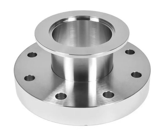
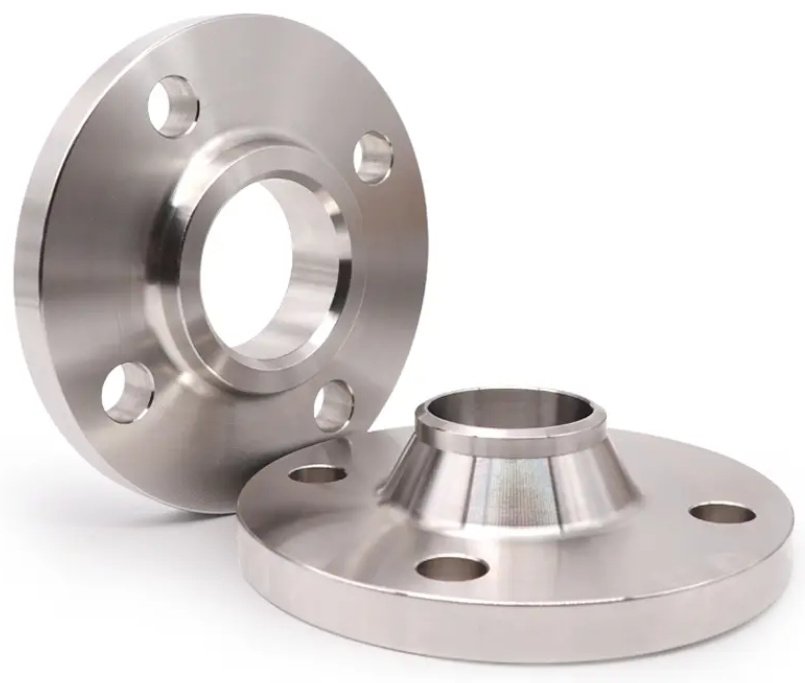
| Weld Neck Flange | High pressure, high temperature, cyclic loading and critical service | Butt-welded to pipe; tapered hub improves stress distribution and weld integrity. |
| Slip-On Flange | General utility piping, low to medium pressure systems | Easy alignment and installation; usually requires two fillet welds. |
| Blind Flange | Pipeline closure, pressure testing, equipment isolation | No center bore; must be selected carefully for pressure, temperature and gasket type. |
| Socket Weld Flange | Small-bore high-pressure piping | Pipe is inserted into socket and fillet welded; commonly used for NPS 2 and below. |
| Threaded Flange | Systems where welding is not preferred | Suitable for selected low-pressure or hazardous-area applications where hot work is restricted. |
| Lap Joint Flange | Systems requiring frequent dismantling or alignment flexibility | Used with stub end; flange can rotate for bolt-hole alignment. |
| Plate Flange | Water, HVAC and low-pressure industrial lines | Cost-effective option when permitted by project standards and pressure conditions. |
When should a weld neck flange be selected instead of a slip-on flange?
A weld neck flange is generally preferred for critical service, higher pressure, higher temperature, vibration, thermal cycling or fatigue-sensitive piping. Compared with a slip-on flange, the weld neck design uses a full-penetration butt weld and a tapered hub that helps reduce stress concentration at the connection.
Standards, Sizes and Pressure Classes
Standard compliance is a key purchasing and engineering requirement. We supply flanges to ASME B16.5, ASME B16.47, EN 1092-1, DIN, JIS B2220 and custom drawing requirements, with dimensional control for outside diameter, bolt circle diameter, number of bolt holes, bolt hole diameter, thickness, bore, hub diameter and facing height.
| Standard | Common Size Range | Common Ratings | Typical Markets |
|---|---|---|---|
| ASME B16.5 | NPS 1/2 to NPS 24 | Class 150, 300, 400, 600, 900, 1500, 2500 | Oil, gas, chemical, power and industrial piping |
| ASME B16.47 | NPS 26 to NPS 60 | Series A and Series B | Large-diameter pipelines and plants |
| EN 1092-1 | DN sizes according to EN system | PN6, PN10, PN16, PN25, PN40 and higher | European water, process and industrial projects |
| DIN Flanges | DN sizes according to DIN drawings | PN ratings by DIN standard | Replacement, maintenance and legacy systems |
| JIS B2220 | Nominal sizes according to JIS | 5K, 10K, 16K, 20K, 30K, 40K and 63K | Asian industrial and marine projects |
Materials and Temperature Suitability
Material selection affects pressure-temperature rating, weldability, corrosion allowance, low-temperature toughness and lifecycle cost. Carbon steel flanges are commonly selected for general industrial service, while low-temperature carbon steel and alloy steel grades are used where operating conditions require improved mechanical performance.
| Material Grade | Material Category | Typical Application |
|---|---|---|
| ASTM A105 / A105N | Carbon steel forging | General pressure piping, oil, gas, water, steam and process lines |
| ASTM A350 LF2 | Low-temperature carbon steel | Low-temperature service requiring impact toughness |
| ASTM A694 F42, F52, F60, F65, F70 | High-yield carbon steel | Transmission pipelines and high-strength applications |
| ASTM A182 F5, F9, F11, F22, F91 | Alloy steel | High-temperature, power plant and refinery service |
| S235JR, P245GH, P250GH, C22.8 | European carbon steel grades | EN and DIN piping projects |
For common ASME carbon steel pipe flanges, ASTM A105N normalized forging is often specified when better grain refinement and more consistent mechanical properties are required. Final selection should be checked against the applicable code, design temperature, fluid, gasket system and corrosion environment.
Material documents that engineers usually request
Typical documents include material test certificate, heat number traceability, chemical composition, tensile test results, hardness records, heat treatment report, impact test results when required, NDE report when specified and dimensional inspection report.
Manufacturing, Machining and Surface Finish
Flange performance depends not only on material grade, but also on forging quality, heat treatment, machining precision and gasket contact surface control. A typical production process includes raw material inspection, cutting, heating, forging, normalizing or quenching and tempering, rough machining, final flange machining, drilling, facing, marking, inspection and protective packaging.
CNC machining, controlled bolt-hole drilling and accurate gasket seating surface preparation help improve assembly efficiency and reduce the risk of leakage caused by poor alignment, uneven contact or surface damage.
| Process | Control Point | Why It Matters |
|---|---|---|
| Forging | Grain flow, deformation ratio, absence of laminations | Improves strength and structural reliability compared with uncontrolled cast or cut parts. |
| Heat Treatment | Normalizing, tempering or grade-specific treatment | Stabilizes mechanical properties and supports code compliance. |
| Turning and Boring | Thickness, bore, hub profile, flange face | Ensures proper fit with pipe schedule, gasket and mating flange. |
| Drilling | Bolt circle diameter, hole quantity, hole diameter | Supports fast installation and avoids field rework. |
| Facing | RF, FF, RTJ groove or special facing | Provides the required gasket compression and sealing interface. |
Common flange face finish requirements
Raised face serrated finishes are commonly controlled by roughness and groove pattern according to project specifications. For many ASME applications, a stock finish is used for compressed fiber, graphite or spiral wound gaskets, while RTJ faces require accurately machined ring grooves with strict dimensional control.
Sealing Performance and Engineering Selection
A flange joint is a system made of two flanges, gasket, bolts, nuts, washers and pipe loads. Leakage is often related to incorrect flange rating, incompatible gasket material, insufficient bolt load, damaged seating surface, flange rotation, misalignment or thermal cycling.
For gasketed joints, surface roughness, bolt load, gasket type and flange rigidity should be evaluated together. A flange with correct dimensions but poor face finish can still fail in service, especially in steam, hydrocarbon, chemical or high-temperature systems.
Practical engineering issue: leakage after repeated shutdowns
In cyclic steam or thermal oil lines, repeated heating and cooling can reduce gasket stress. An engineering review often checks flange class, bolt material, gasket design, tightening sequence and flange face condition. Replacing a low-rigidity connection with a correctly rated weld neck flange and controlled spiral wound gasket can reduce flange rotation and improve joint stability during thermal cycling.
Data points engineers commonly verify
- Pressure-temperature rating: verified by material group and flange class rather than nominal pressure alone.
- Pipe schedule and bore: matched to pipe wall thickness to avoid internal mismatch.
- Gasket seating width: checked for gasket compression and sealing stress.
- Bolt circle and hole diameter: measured to avoid installation delay at site.
- Face condition: inspected for scratches, dents, corrosion and machining marks.
Inspection, Testing and Documentation
Quality control should be linked to the risk level of the piping system. For standard industrial supply, dimensional inspection, visual inspection and material verification are typically required. For critical projects, additional nondestructive testing and third-party inspection can be arranged according to the purchase specification.
| Inspection Item | Typical Method | Purpose |
|---|---|---|
| Material Verification | MTC review, PMI when required | Confirms grade, heat number and chemical composition. |
| Dimensional Inspection | Caliper, micrometer, gauge, template | Checks OD, ID, thickness, bolt circle, bolt holes and facing. |
| Visual Inspection | Surface review under controlled lighting | Identifies cracks, folds, dents, corrosion or handling damage. |
| NDE | UT, MT, PT or RT as specified | Detects internal or surface defects for critical service. |
| Hardness Test | Portable or bench hardness tester | Verifies heat treatment consistency and material condition. |
| Marking Check | Visual and document comparison | Confirms size, rating, material, heat number and standard marking. |
For traceable supply, EN 10204 3.1 material certificates, heat number marking and dimensional reports are commonly provided. Third-party inspection by agencies such as SGS, BV, TUV or Lloyd’s can be supported when specified by the buyer or project owner.
Buyer and Engineer Specification Checklist
A clear specification reduces quotation errors, production delays and field mismatch. The most frequent purchasing problems are caused by missing pressure class, unspecified face type, unclear material normalization requirement, wrong pipe schedule or incomplete standard reference.
| Required Information | Example | Reason |
|---|---|---|
| Standard | ASME B16.5 | Defines dimensions, ratings and tolerances. |
| Size | NPS 6 or DN150 | Determines bore, flange OD and bolt pattern. |
| Pressure Rating | Class 300 or PN40 | Controls thickness, bolt size and pressure-temperature capability. |
| Type | Weld neck, slip-on, blind, socket weld | Determines connection method and installation process. |
| Facing | RF, FF, RTJ | Must match gasket type and mating flange. |
| Material | ASTM A105N, A350 LF2, A182 F22 | Defines mechanical properties, temperature suitability and weldability. |
| Pipe Schedule or Bore | SCH 40, SCH 80, XS, XXS | Ensures correct fit-up and internal diameter matching. |
| Coating or Finish | Black paint, anti-rust oil, galvanized, epoxy coating | Protects during transport, storage and operation. |
| Documents | MTC 3.1, inspection report, packing list | Supports project acceptance and traceability. |
A complete purchase specification should include standard, size, class, type, face, material, pipe schedule, quantity, coating and documentation requirements. For replacement projects, photos of existing markings and measured dimensions can help avoid standard mismatch.
Common causes of flange procurement mismatch
The most common issues include confusing ANSI and DIN bolt patterns, specifying nominal size without pressure class, ordering RF when FF is required for cast iron equipment, selecting a bore that does not match pipe schedule, and omitting normalization or impact testing requirements for low-temperature service.
Typical Applications
Steel flanges are used wherever a strong, removable and inspectable pipe joint is required. They are suitable for new construction, plant maintenance, pipeline repair, skid fabrication, pressure equipment assembly and pump or valve connection.
- Oil and gas pipelines, gathering stations and terminals
- Refineries, petrochemical plants and chemical process lines
- Power plants, boiler systems, steam lines and cooling water systems
- Water supply, wastewater treatment and desalination projects
- Shipbuilding, offshore platforms and marine piping systems
- Mining slurry lines, compressed air, fire protection and utility piping
- Equipment nozzles, pressure vessels, heat exchangers, pumps and valves
Surface Protection, Packing and Traceability
Finished flanges can be supplied with anti-rust oil, black paint, yellow paint, zinc coating, hot-dip galvanizing, epoxy coating or other project-specified protection. Sealing faces are protected to reduce damage during transport and storage.
Standard packing options include plywood cases, wooden pallets, steel-framed pallets and seaworthy export packaging. Each package can be labeled with size, rating, material, heat number, quantity, gross weight, net weight and purchase order information for warehouse identification.
- Marking: standard, size, class, material grade, heat number and manufacturer mark
- Traceability: heat number linked to material certificate and inspection record
- Protection: flange face cover, rust prevention and moisture-resistant packaging
- Logistics: batch labeling for project lots, shutdown maintenance orders and multi-site delivery
Reference Standards and Engineering Notes
Steel flange selection should follow the project piping class, applicable design code and end-user specification. Commonly referenced standards include ASME B16.5 for pipe flanges and flanged fittings, ASME B16.47 for large diameter steel flanges, ASME B16.20 for metallic gaskets, ASME B31.3 for process piping, EN 1092-1 for circular flanges and ASTM material standards for forged carbon and alloy steel components.
For safe operation, pressure class should not be interpreted as working pressure without checking material group and temperature. Gasket, bolting, flange face and installation procedure must be considered as one sealing system.