Metal tapping is the machining process used to create internal threads in a drilled hole so that screws, bolts, studs, or threaded inserts can be assembled securely. It is widely used in CNC machining, metal fabrication, automotive parts, aerospace components, electronics housings, hydraulic manifolds, fixtures, and custom hardware.
A successful tapping operation depends on hole preparation, tap geometry, material condition, lubrication, spindle control, chip evacuation, and thread tolerance. For engineers and buyers, the goal is not only to produce a threaded hole, but to obtain a repeatable, inspection-ready feature with controlled cost, predictable tool life, and low assembly risk.
What Is Metal Tapping?
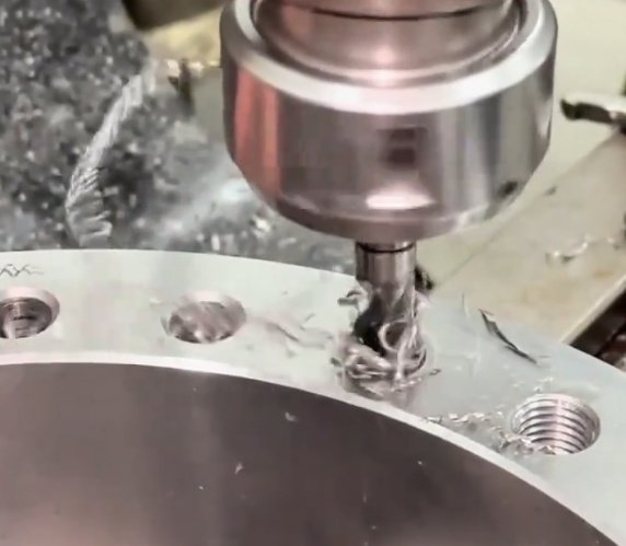
Metal tapping is a secondary machining operation in which a tool called a tap cuts or forms a helical thread inside a pre-drilled hole. The hole diameter before tapping is called the tap drill size. If the hole is too small, torque rises sharply and taps may break. If it is too large, thread engagement becomes weak and the fastener may fail under load.
In most production environments, tapping is performed on CNC machining centers, turning centers, drill presses, tapping arms, or dedicated thread-tapping machines. The operation can be used for metric threads, UNC, UNF, BSP, NPT, and other thread standards depending on the application.
Thread quality is controlled before the tap enters the hole: hole straightness, drill diameter, chamfer, burr condition, and coolant access all influence the final internal thread.
Common Metal Tapping Methods
The best tapping method depends on the workpiece material, hole type, production volume, thread depth, and required tolerance. The two main categories are cutting taps and forming taps.
| Method | How It Works | Best For | Key Consideration |
|---|---|---|---|
| Cutting Tap | Removes material to generate the thread profile | Steel, stainless steel, cast iron, titanium, brass, and general metals | Requires chip control and lubrication |
| Forming Tap | Displaces material plastically without producing chips | Aluminum, copper, brass, mild steel, and ductile alloys | Needs correct hole size and sufficient ductility |
| Rigid Tapping | CNC spindle rotation is synchronized with feed rate | High-volume CNC machining and repeatable thread depth | Requires accurate machine synchronization |
| Thread Milling | A milling cutter interpolates the internal thread | Large threads, hard materials, expensive parts, and blind holes | Slower than tapping but safer for high-value components |
When is thread milling better than tapping?
Thread milling is often preferred when the part is expensive, the thread diameter is large, the material is difficult to machine, or broken-tap removal would cause unacceptable scrap cost. It also allows one tool to produce different thread diameters with the same pitch, provided the CNC machine supports helical interpolation.
Tap Types and Their Applications
Choosing the right tap is one of the most important decisions in metal tapping. A tap that works well in a through hole may fail quickly in a blind hole because chip direction, flute design, and coolant flow are different.
| Tap Type | Application | Chip Behavior | Typical Use Case |
|---|---|---|---|
| Straight Flute Tap | General-purpose tapping | Chips remain in flutes | Cast iron, brass, shallow holes |
| Spiral Point Tap | Through holes | Pushes chips forward | Steel plates, brackets, through-threaded holes |
| Spiral Flute Tap | Blind holes | Pulls chips upward | Aluminum housings, mold plates, manifolds |
| Pipe Tap | Tapered pipe threads | Depends on design | NPT, BSPT hydraulic and pneumatic ports |
| Forming Tap | Chipless internal threads | No chips generated | Ductile aluminum, copper alloys, mild steel |
For blind hole tapping, spiral flute taps reduce chip packing and help prevent bottom-of-hole breakage. For through hole tapping, spiral point taps are commonly more stable because chips are driven ahead of the tool and out of the workpiece.
Material-Specific Tapping Recommendations
Different metals behave differently during tapping. Hardness, ductility, thermal conductivity, work hardening, and chip shape all affect tap selection and metal machining parameters.
| Material | Tapping Behavior | Recommended Approach | Common Risk |
|---|---|---|---|
| Aluminum Alloys | Soft, ductile, may build up on cutting edges | Use sharp taps, polished flutes, suitable coolant, or forming taps | Built-up edge and oversized threads |
| Carbon Steel | Moderate cutting resistance and predictable chips | Use coated HSS or carbide taps with cutting oil or coolant | Tap wear and torque increase |
| Stainless Steel | Work-hardening and high friction | Use high-performance taps, lower speed, rich lubrication | Galling, work hardening, tap breakage |
| Cast Iron | Short, abrasive chips | Use straight flute or coated taps; often dry or mist machining | Abrasive wear and poor surface finish |
| Titanium | Low thermal conductivity and elastic recovery | Use rigid setup, sharp premium taps, controlled speed, high-pressure coolant | Heat concentration and thread distortion |
| Brass and Bronze | Generally free-machining but alloy-dependent | Use geometry matched to alloy and avoid excessive rake | Grabbing, chatter, or torn threads |
Stainless steel tapping requires special attention because work hardening can occur if the tap rubs instead of cuts. Once the material surface hardens, torque rises and tool failure becomes more likely.
Tap Drill Size, Thread Engagement, and Hole Preparation
Tap drill size determines the percentage of thread engagement. Many engineers specify 60% to 75% thread engagement for general metal parts because it balances strength, torque, and tool life. Higher engagement does not always mean better performance; it can significantly increase tapping torque while adding little practical joint strength.
Typical tap drill formulas include:
- Metric cutting tap approximation: tap drill diameter = major diameter - pitch
- Imperial cutting tap approximation: tap drill diameter = major diameter - 1 / threads per inch
- Forming tap drill diameter: normally larger than cutting tap drill size and must follow tap manufacturer data
Example: for an M6 × 1.0 cutting tap, the common drill size is approximately 5.0 mm. For a forming tap in the same thread, the recommended hole may be larger, often around 5.45 mm to 5.55 mm depending on material and thread percentage.
Chamfering the hole before tapping improves tap entry, reduces first-thread damage, and helps assembly. For precision threaded holes, the drilling process should be controlled for runout, burrs, and hole depth before tapping begins.
Why can a larger tap drill improve production results?
In many metal parts, reducing thread engagement from about 75% to about 65% can lower tapping torque while maintaining adequate thread strength for the intended fastener load. This may increase tap life, reduce broken taps, and improve cycle stability. Final approval should be based on thread standard, material strength, fastener grade, and assembly load.
Cutting Speed, Feed Rate, Torque, and Lubrication
In tapping, feed rate must match thread pitch. If the machine does not synchronize spindle speed and feed correctly, the tap can stretch, compress, cut oversized threads, or break. CNC rigid tapping solves this by coordinating spindle rotation with Z-axis feed.
General starting ranges for cutting taps vary by tool supplier, coating, coolant, and material condition, but the following values are common reference ranges for engineering planning:
| Material | Typical Cutting Speed Range | Lubrication Preference |
|---|---|---|
| Aluminum | 20–60 m/min | Soluble coolant, tapping fluid, or mist |
| Mild Steel | 8–25 m/min | Cutting oil or high-quality coolant |
| Stainless Steel | 3–12 m/min | High-lubricity tapping oil or rich coolant |
| Cast Iron | 10–30 m/min | Dry, mist, or light coolant depending on grade |
| Titanium | 2–8 m/min | High-pressure coolant or premium tapping fluid |
Torque monitoring is a practical quality signal in high-volume tapping. A gradual increase in torque can indicate tool wear, poor lubrication, chip packing, or undersized drilled holes. A sudden spike may indicate misalignment, hard spots, or imminent tap fracture.
Engineering Problems in Metal Tapping and Measurable Improvements
Metal tapping failures are often expensive because a broken tap may be harder than the surrounding workpiece and difficult to remove. In CNC production, one broken tap can scrap a finished part after multiple previous machining operations have already consumed time and cost.
| Problem | Likely Cause | Engineering Correction | Expected Result |
|---|---|---|---|
| Broken tap in blind hole | Chip packing or insufficient bottom clearance | Use spiral flute tap, increase hole depth allowance, improve coolant access | Lower breakage and more consistent thread depth |
| Oversized thread | Runout, worn tap, poor synchronization | Check holder, use rigid tapping, replace worn tool | Improved go/no-go gauge consistency |
| Rough thread surface | Incorrect tap coating, poor lubrication, built-up edge | Use polished or coated tap, select better fluid, reduce speed if needed | Cleaner flank finish and easier assembly |
| Short tap life | Excessive thread engagement or wrong drill size | Review tap drill size and thread percentage | Reduced tool cost per threaded hole |
| Thread gauge failure | Wrong tolerance class or thermal/tool deflection | Confirm thread standard, inspect hole diameter, validate tool path | Higher first-pass inspection rate |
A real production improvement often comes from combining several small changes. For example, in an aluminum housing with M5 blind holes, changing from a general-purpose straight flute tap to a spiral flute tap, adding a controlled entry chamfer, and verifying tap drill diameter can reduce chip-related failures substantially. In many shops, this type of process correction can reduce broken taps by 50% or more, depending on the original setup stability.
What data should be collected during tapping process validation?
Useful data includes drilled hole diameter, hole depth, chamfer size, tap type, coating, speed, coolant type, torque trend, number of holes per tap, go/no-go gauge results, thread depth, part material certification, and scrap reason. This information helps engineering and purchasing teams compare tooling cost against thread quality and cycle stability.
Inspection and Thread Quality Control
Internal thread inspection usually includes dimensional checks, functional gauging, visual inspection, and sometimes destructive testing. The correct method depends on part criticality and industry requirements.
- Go/no-go plug gauges verify whether the internal thread is within the specified tolerance class.
- Thread depth gauges confirm that the usable thread length meets the drawing requirement.
- Optical or borescope inspection can help identify burrs, torn threads, or incomplete thread forms.
- Torque testing may be used for assembly-critical threaded holes.
- Pull-out testing can validate thread strength in soft metals or thin-wall components.
Thread tolerance must match the drawing and assembly requirement. Common specifications include metric 6H internal threads and unified 2B or 3B internal threads. A tighter tolerance can improve fit but may increase manufacturing cost and rejection risk if the process is not controlled.
Buyer and Procurement Considerations for Metal Tapped Parts
For sourcing metal parts with tapped holes, the drawing should define thread size, pitch, tolerance class, thread depth, hole depth, material, surface treatment, and any post-processing that may affect thread fit. Plating, anodizing, heat treatment, and coating thickness can change internal thread dimensions.
Buyers should evaluate suppliers based on machining capability, inspection equipment, process documentation, tap life control, and experience with the required material. Low unit price is not the only cost factor; thread failure can cause assembly delays, warranty claims, rework, and scrapped parts.
| Purchasing Question | Why It Matters |
|---|---|
| Can the supplier inspect internal threads with calibrated gauges? | Ensures thread tolerance is verified rather than assumed |
| Does the process account for plating or anodizing buildup? | Prevents tight or rejected threads after surface treatment |
| Is the tapped hole blind or through? | Affects tap type, chip evacuation, and bottom clearance |
| What is the minimum wall thickness around the thread? | Reduces risk of cracking, distortion, or weak thread engagement |
| Is thread forming acceptable instead of thread cutting? | May improve strength and eliminate chips in ductile materials |
Design Tips for Reliable Metal Tapping
Good thread design improves manufacturability and reduces cost. Engineers can often prevent tapping problems by allowing enough thread depth, avoiding unnecessary tight tolerances, specifying realistic hole depths, and selecting thread sizes compatible with the part geometry.
- Use standard thread sizes whenever possible to reduce tooling cost and lead time.
- Provide sufficient bottom clearance for blind holes, especially when full thread depth is required.
- Avoid placing tapped holes too close to thin walls, edges, or intersecting holes.
- Specify whether threads must be clean after coating, plating, or anodizing.
- Use thread inserts for soft metals if repeated assembly and disassembly are expected.
- Consider forming taps for ductile materials when chip contamination is unacceptable.
- Match fastener engagement length to material strength instead of over-specifying thread depth.
A common design guideline is that steel threaded holes may need about 1 times the fastener diameter of engagement for many general applications, while aluminum may require about 1.5 to 2 times the diameter depending on load, alloy, and fastener grade. Critical applications should be verified by engineering calculation or testing.
Key Takeaways
Metal tapping is a small operation with major influence on assembly reliability, production yield, and part cost. Accurate internal threads require the correct tap type, drill size, coolant strategy, machine synchronization, and inspection method.
The best tapping process is material-specific and application-specific. Through holes, blind holes, stainless steel parts, aluminum housings, cast iron components, and titanium parts each require different decisions. By controlling hole preparation, chip evacuation, torque, lubrication, and thread tolerance, manufacturers can improve tap life, reduce scrap, and deliver threaded components that meet engineering and purchasing expectations.
Technical references commonly used for tapping decisions include tap manufacturer catalogs, ISO and ASME thread standards, Machinery’s Handbook, material datasheets, and internal process validation records. For production-critical parts, documented testing remains the most reliable way to confirm thread strength, tool life, and inspection repeatability.