Metal threading is the process of creating helical grooves on or inside metal parts so that bolts, nuts, studs, inserts, shafts, pipe fittings, and precision assemblies can connect securely. In manufacturing, threading is not only a fastening operation; it affects load capacity, sealing performance, fatigue life, assembly speed, maintenance access, and total part cost.
This guide explains how metal threads are made, which thread standards are commonly used, how materials affect tooling and thread quality, and what engineers and buyers should specify to avoid scrap, weak threads, galling, or assembly failure.
What Is Metal Threading?
Metal threading forms a continuous helical ridge known as a thread. When the thread is produced on the outside of a cylindrical part, it is an external thread, such as a bolt, screw, threaded rod, or shaft end. When the thread is produced inside a hole, it is an internal thread, such as a tapped hole, nut, or threaded port.
A functional thread is defined by several geometry terms:
- Major diameter: the largest diameter of an external thread or the largest internal thread diameter.
- Minor diameter: the smallest diameter at the thread root.
- Pitch: the distance from one thread crest to the next, commonly in millimeters for metric threads.
- Threads per inch: the number of thread peaks per inch, used for inch-based UNC, UNF, NPT, and related standards.
- Thread angle: the included angle between thread flanks, typically 60 degrees for ISO metric and Unified threads.
- Lead: the linear travel per full revolution; for single-start threads, lead equals pitch.
- Class of fit: the allowance and tolerance controlling looseness or tightness between mating threads.
For engineering applications, metal threading must be specified as a controlled feature, not treated as a generic machining note. A thread that appears acceptable visually may still fail a go/no-go gauge, leak under pressure, seize during assembly, or strip under torque.
Common Metal Thread Types and Standards
Thread standards define geometry, tolerances, and compatibility. Choosing the correct standard is essential for interchangeable parts, field service, and international sourcing.
| Thread Type | Typical Use | Key Characteristics |
|---|---|---|
| ISO Metric Thread | Machinery, automotive, industrial equipment, electronics | Specified as M diameter × pitch, such as M6 × 1.0; 60-degree profile |
| UNC Thread | General inch fasteners, structural assemblies | Coarse Unified thread; better for softer metals and quick assembly |
| UNF Thread | Precision assemblies, aerospace, hydraulic components | Fine Unified thread; higher adjustment resolution and stronger minor diameter |
| NPT Thread | Pipe fittings, fluid and gas connections | Tapered thread designed for sealing with interference and sealant |
| BSPP and BSPT | Pipe connections, hydraulic and pneumatic systems | British Standard Pipe; parallel or tapered versions |
| ACME Thread | Lead screws, jacks, vises, linear motion systems | Trapezoidal form designed for power transmission |
| Buttress Thread | High axial load in one direction | Asymmetric flank profile for load-bearing applications |
Metric threads are often specified with tolerance classes such as 6H for internal threads and 6g for external threads. Unified inch threads commonly use classes such as 2A, 2B, 3A, and 3B, where A refers to external threads and B refers to internal threads. Class 2 is widely used for general assembly, while Class 3 is used for tighter precision fits.
Metal Threading Processes
Different manufacturing methods can produce threads, and the best choice depends on material, thread size, quantity, strength requirement, tolerance, and access to the threaded feature. The main processes include tapping, thread milling, single-point threading, die threading, thread rolling, and thread grinding.
Tapping for Internal Threads
Tapping uses a cutting tap or forming tap to create internal threads in a drilled hole. It is common in CNC machining, manual machining, and production drilling operations. Cutting taps remove chips, while forming taps displace metal without producing chips.
Cutting taps are versatile and suitable for many steels, stainless steels, cast irons, and aluminum alloys. Forming taps are preferred for ductile materials such as aluminum, brass, copper, and some steels because they can produce stronger threads with improved surface finish. However, forming taps require accurate hole size control and higher torque.
Thread Milling
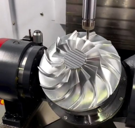
Thread milling uses a rotating cutter that follows a helical toolpath to generate internal or external threads. It is especially useful for large thread diameters, blind holes, hard materials, expensive parts, and applications where broken taps are unacceptable.
One thread mill can often machine multiple thread sizes with the same pitch, reducing tooling inventory. Thread milling also allows controlled entry and exit, easier chip evacuation, and accurate thread depth in blind holes. In CNC machining, it is often the preferred method for aerospace, medical, mold, and high-value components.
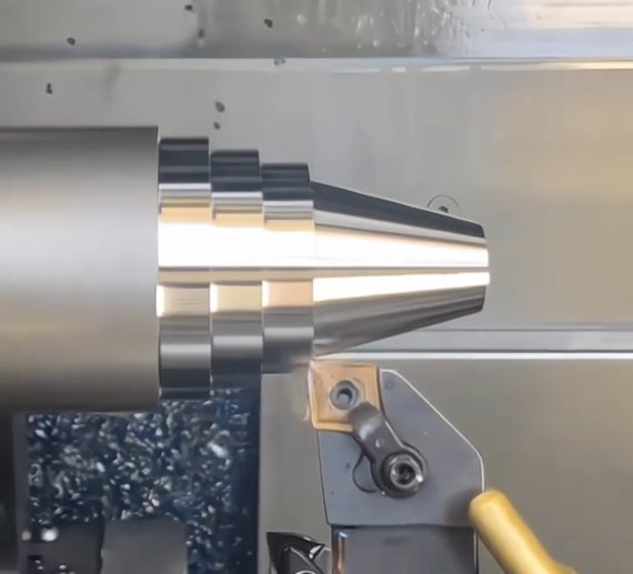
Single-Point Threading on a Lathe
Single-point threading uses a shaped tool on a lathe to cut external or internal threads. It is commonly used for shafts, threaded pins, custom thread forms, large diameters, and low-volume precision work. CNC lathes can cut metric, inch, tapered, multi-start, and special profile threads with high repeatability.
Die Threading
Die threading cuts external threads using a round die or die head. It is suitable for rods, studs, pipe ends, and repair work. For high production, self-opening die heads can improve cycle time and consistency. Die threading is usually less flexible than CNC single-point threading but can be economical for standard external threads.
Thread Rolling
Thread rolling is a cold forming process that displaces metal between hardened dies rather than cutting it. It is widely used for high-volume fasteners, studs, screws, and shaft threads. Rolled threads typically provide better fatigue resistance because the grain flow follows the thread profile and the root surface is work-hardened.
Compared with cut threads, rolled threads can increase fatigue strength by approximately 20% to 60% in many fastener applications, depending on material, geometry, surface finish, and loading condition. The process requires ductile material and precise blank diameter control.
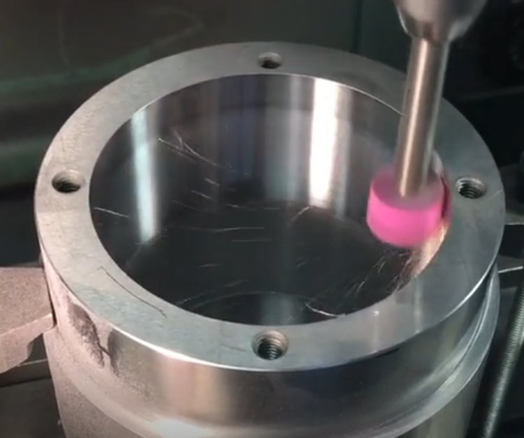
Thread Grinding
Thread grinding is used for very high precision threads, hardened materials, lead screws, gauges, worms, and aerospace components. It provides excellent pitch accuracy and surface finish, but it is slower and more expensive than cutting or rolling.
Quick selection guide: cutting, forming, milling, or rolling?
Use cutting taps for general internal threads in moderate-volume production. Use forming taps when the material is ductile and chip control is critical. Use thread milling for large, blind, hard, or high-value parts. Use thread rolling when external thread strength, production volume, and fatigue performance are more important than process flexibility.
Material-Specific Engineering Considerations
Material behavior strongly affects thread quality, tool life, chip evacuation, and torque capacity. A thread design that works in 6061 aluminum may fail or become uneconomical in 316 stainless steel or titanium.
| Material | Threading Behavior | Practical Recommendation |
|---|---|---|
| Aluminum alloys | Easy to machine, but soft threads can strip under high load | Use coarse threads, sufficient engagement length, or thread inserts for repeated assembly |
| Carbon steel | Good machinability depending on grade and hardness | Use appropriate cutting oil and consider rolling for high-strength external threads |
| Stainless steel | Work hardens, generates stringy chips, prone to galling | Use sharp tools, rigid setup, high-pressure coolant, and anti-galling surface treatment |
| Titanium | Low thermal conductivity, high cutting temperature, strong tendency to gall | Use conservative speeds, rigid tooling, premium coolant, and avoid rubbing cuts |
| Brass and bronze | Generally machinable; chip behavior depends on alloy | Select tool geometry based on free-machining or tough bronze grade |
| Cast iron | Short chips, abrasive structure | Use wear-resistant tools and account for dust-like chips during tapping |
For repeated assembly in aluminum or magnesium housings, thread inserts can significantly improve service life. Helical inserts, key-locking inserts, and solid threaded bushings are common solutions when the parent metal cannot provide enough pull-out strength or wear resistance.
Design Rules for Reliable Metal Threads
Good thread design balances strength, manufacturability, assembly access, and inspection. The following rules are widely used in machined metal parts.
Choose the Correct Thread Engagement Length
Thread engagement length is the axial length over which internal and external threads contact. Too little engagement can cause stripping; too much engagement increases machining time without meaningful strength gain.
As a practical starting point, steel-to-steel joints often use about 1× nominal diameter of thread engagement. Aluminum and softer metals may require 1.5× to 2× diameter, depending on load, pitch, alloy strength, and whether inserts are used. For critical joints, calculate shear area and verify against material yield and proof load.
Avoid Threading to the Bottom of Blind Holes
Blind holes need extra depth for drill point clearance, tap chamfer, chip accumulation, and tool overtravel. If a drawing calls for full thread depth to the bottom, manufacturing risk increases sharply. A bottoming tap can get closer than a taper or plug tap, but it still needs relief.
A common CNC machining rule is to drill deeper than the required full thread length by at least 1 to 2 thread diameters when geometry allows. In shallow blind holes, thread milling may produce more controlled full-thread depth than tapping.
Provide Chamfers and Lead-In Features
Chamfers reduce burrs, guide fasteners during assembly, and prevent cross-threading. External threads typically need a chamfered start or turned relief. Internal threads benefit from countersinks or entry chamfers, especially in automated assembly.
Account for Coatings and Plating
Zinc plating, anodizing, nickel plating, black oxide, passivation, and dry-film lubricants can change thread fit. Internal threads may become tight after coating, while external threads may exceed maximum material limits. For coated components, specify whether thread inspection is required before or after surface treatment.
In precision parts, thread tolerance should be matched to the final surface condition. For example, anodized aluminum threads may need masking, post-process chasing, or adjusted pre-coating dimensions.
Tap drill size and percent thread: why 100% thread is rarely ideal
Many standard tap drill charts target approximately 60% to 75% thread height because this range provides most of the thread strength while reducing tapping torque and tool breakage. A 100% theoretical thread height can greatly increase torque with limited strength benefit. In ductile metals, lower percent thread may improve tool life and reduce scrap without compromising functional performance.
Tolerances, Inspection, and Quality Control
Thread quality cannot be confirmed by visual inspection alone. A properly controlled metal threading process should define measurement method, gauge type, acceptance criteria, and inspection timing.
Go/No-Go Thread Gauges
Go/no-go gauges are the most common shop-floor inspection tools. A go gauge verifies that the thread is not too tight, while a no-go gauge checks that it is not too loose or oversize. Plug gauges are used for internal threads, and ring gauges are used for external threads.
Pitch Diameter Measurement
Pitch diameter is a critical functional dimension because it controls thread fit. External pitch diameter can be measured with the three-wire method, thread micrometers, optical comparators, or coordinate measuring machines. Internal pitch diameter may require specialized gauges or CMM strategies.
Surface Finish and Burr Control
Thread surface finish affects friction, torque-tension relationship, fatigue resistance, and sealing. Burrs at thread starts can cause cross-threading, assembly jams, or contamination in hydraulic and medical components. Deburring methods include chamfering, brushing, thermal deburring, abrasive flow, manual deburring, and controlled toolpath exits.
Common Thread Defects
- Oversized internal thread: wrong tap, excessive tool wear compensation, loose setup, or coating removal.
- Undersized internal thread: incorrect drill size, plating buildup, work hardening, or dull forming tap.
- Torn thread flanks: poor lubrication, wrong cutting speed, dull tool, or unstable workholding.
- Bell-mouthed thread: tool deflection or misalignment at thread entry.
- Broken tap: chip packing, insufficient hole depth, excessive torque, or poor synchronization.
- Galling: adhesive wear, usually in stainless steel, titanium, aluminum, or similar metal pairs.
For production control, thread inspection should reflect the actual assembly requirement. A decorative threaded cover may need a different control plan than a pressure port, structural bolt hole, aerospace insert, or rotating lead screw.
Real Engineering Problems and Data-Driven Fixes
Metal threading failures often appear during assembly, not during machining. The following practical cases show how small design and process changes can reduce defects.
Case 1: Broken Taps in 316 Stainless Steel
A CNC shop machining 316 stainless steel manifolds experienced frequent M8 × 1.25 tap breakage in blind holes. The root causes were chip packing, insufficient coolant delivery, and a drill depth that left minimal clearance below the full thread requirement.
Corrective actions included increasing drill depth by 2.5 mm, switching from tapping to thread milling for the blind holes, and adding through-spindle coolant. Scrap caused by broken taps dropped from 3.8% to below 0.5% over the next production batch. Cycle time increased slightly, but the reduction in rejected manifolds improved total cost per accepted part.
Case 2: Aluminum Threads Stripping During Service
An aluminum equipment housing used M5 screws removed during routine maintenance. After repeated service cycles, internal threads began stripping. The original thread engagement was only 5 mm in 6061-T6 aluminum, with steel screws tightened by hand tools.
The fix was to increase engagement to 8 mm where possible and install stainless helical inserts in high-service locations. Pull-out resistance improved, and field returns related to stripped threads were reduced by more than 70% over six months.
Case 3: Stainless Fasteners Galling in Assembly
A buyer reported that stainless steel bolts and nuts seized before reaching the specified torque. Inspection showed correct thread dimensions, but the combination of similar stainless grades, dry assembly, and high installation speed caused galling.
The solution used silver-plated nuts for critical joints, reduced assembly speed, and applied approved anti-seize lubricant on non-cleanroom hardware. The torque scatter decreased, and assembly stoppages were largely eliminated.
Troubleshooting checklist for poor metal thread quality
- Confirm the thread standard, pitch, and tolerance class against the drawing.
- Check tap drill diameter or pre-roll blank diameter before threading.
- Inspect tool wear, coating condition, and tool runout.
- Verify coolant type, concentration, pressure, and delivery direction.
- Review chip evacuation in blind holes and deep threads.
- Inspect after coating if plating or anodizing affects fit.
- Use calibrated go/no-go gauges at defined inspection intervals.
Cost, Lead Time, and Procurement Considerations
For buyers and sourcing engineers, the lowest quoted unit price is not always the lowest total cost. Threaded features can drive tooling cost, inspection time, scrap risk, and lead time, especially when a part has deep blind holes, tight thread classes, exotic material, or post-plating requirements.
Key cost drivers include:
- Thread size and depth: deep small-diameter threads increase tool breakage risk.
- Material hardness and work hardening: stainless steel, Inconel, titanium, and hardened steels require slower machining and better tooling.
- Thread quantity per part: many tapped holes can dominate cycle time.
- Blind vs through holes: blind holes are more difficult for chip control and full-depth threading.
- Tolerance class: tighter thread fits require better process control and inspection.
- Surface treatment: plating or anodizing may require masking, allowance changes, or post-process thread cleaning.
- Inspection requirements: certified gauges, CMM reports, or first article inspection add time and cost.
From a procurement perspective, a clear thread specification reduces supplier interpretation risk. A drawing that only says “tap M6” may produce inconsistent results, while “M6 × 1.0 - 6H, full thread depth 12 mm, inspect after anodizing” gives the manufacturer measurable requirements.
| Requirement | Low-Risk Specification Example | Why It Matters |
|---|---|---|
| Internal metric thread | M10 × 1.5 - 6H | Defines diameter, pitch, and tolerance class |
| External inch thread | 1/4-20 UNC-2A | Defines thread series and fit class |
| Blind hole depth | Thread depth 15 mm minimum; drill depth 20 mm minimum | Prevents tool bottoming and incomplete threads |
| Coated thread | Thread gauge inspection after zinc plating | Ensures final assembly fit |
| Pressure port | 1/8-27 NPTF, leak test per specified pressure | Controls sealing performance, not just thread geometry |
Machining Parameters and Process Planning
Threading parameters depend on machine rigidity, tool material, coating, workpiece alloy, coolant, thread depth, and required finish. Although every shop should validate parameters with tooling supplier data, several principles are broadly reliable.
Cutting Speed and Feed
In tapping, feed must match thread pitch. For example, an M6 × 1.0 tap advances 1.0 mm per spindle revolution. In rigid tapping, spindle rotation and feed are synchronized by the CNC control. Any mismatch can overload the tap and distort threads.
In thread milling, feed is programmed along a helical path. Programmers must compensate for cutter diameter and circular interpolation effects, especially on small internal threads. Toolpath entry should avoid leaving a witness mark at a functional sealing surface.
Coolant and Lubrication
Threading usually benefits from high lubricity because thread flanks have large contact area and friction. Stainless steel and titanium often require premium cutting fluids, while aluminum may benefit from lubricants that prevent built-up edge. For blind holes, coolant pressure and chip evacuation can matter more than nominal cutting speed.
Tool Coatings and Substrates
High-speed steel taps remain common for general work, while carbide tools are used for thread milling, abrasive materials, and high-volume production. Coatings such as TiN, TiCN, TiAlN, AlCrN, DLC, and oxide treatments can improve wear resistance, reduce friction, or prevent built-up edge depending on the metal being threaded.
For difficult alloys, tool geometry is as important as tool coating. Flute design, rake angle, chamfer length, relief, and coolant-through capability can determine whether chips evacuate cleanly or pack inside the hole.
Specifying Metal Threading on Drawings and RFQs
A complete thread specification helps manufacturers quote accurately and produce parts consistently. When sending a drawing, 3D model, or request for quotation, include the functional requirements rather than assuming the supplier will infer them.
Recommended information includes:
- Thread standard, diameter, pitch, and tolerance class.
- Internal or external thread location and orientation.
- Required full thread depth and total hole depth for blind holes.
- Material grade, condition, and hardness.
- Surface treatment, coating thickness, and whether threads are masked.
- Inspection method, gauge requirement, and reporting level.
- Assembly function, such as structural fastening, sealing, adjustment, or repeated service.
- Expected production volume and batch size.
When thread performance is critical, consider adding torque requirements, pull-out force, proof load, leak test pressure, or cycle-life targets. These functional requirements help align machining, inspection, and material selection with the real application.
Key Takeaways
Metal threading is a precision manufacturing operation that directly affects product reliability. The best threading method depends on thread type, material, tolerance, production volume, and assembly function. Tapping is efficient for many internal threads, thread milling is safer for complex or high-value parts, single-point threading offers flexibility, and thread rolling delivers superior external thread strength in high-volume production.
To improve quality and reduce cost, specify thread standards clearly, allow adequate hole depth, control coating effects, inspect with proper gauges, and match the process to the material. Well-designed metal threads reduce assembly problems, prevent field failures, and make machined components easier to manufacture at scale.