Metal boring is a machining process used to enlarge, straighten, and finish an existing hole in a metal workpiece. Unlike drilling, which creates the initial hole, boring improves hole diameter accuracy, roundness, straightness, concentricity, and surface finish. It is widely used in CNC machining, heavy equipment repair, aerospace components, hydraulic cylinders, engine blocks, gearbox housings, molds, dies, and large structural parts.
For engineers, machinists, and procurement teams, the main search intent behind metal boring is usually practical: how the process works, what tolerances are realistic, which boring method is suitable, how tooling affects quality, and what information should be included in a machining drawing or RFQ.
What Is Metal Boring?
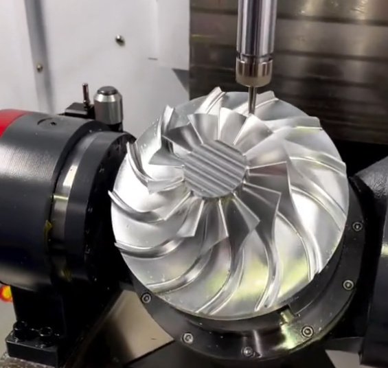
Metal boring is an internal turning operation performed with a single-point or multi-point cutting tool. The tool removes material from the inner diameter of a pre-existing hole. The workpiece may rotate, as in lathe boring, or the boring tool may rotate, as in a machining center or horizontal boring mill.
The process is commonly used after drilling, casting, forging, flame cutting, or rough machining when the hole must meet tighter dimensional or geometric requirements. Boring can correct many hole errors that drilling alone cannot, including tapered holes, misalignment, out-of-round conditions, bell-mouth openings, and poor surface finish.
| Process | Main Purpose | Typical Result |
|---|---|---|
| Drilling | Create the initial hole | Fast material removal, moderate accuracy |
| Boring | Improve hole size, position, and geometry | Accurate diameter, better straightness and concentricity |
| Reaming | Finish a prepared hole to size | Good surface finish, limited correction of hole location |
| Honing | Improve surface texture and roundness | Fine finish and controlled crosshatch pattern |
Common Metal Boring Methods
The best boring method depends on part size, material, hole depth, tolerance, production volume, and whether the component is new production or repair work.
CNC Lathe Boring
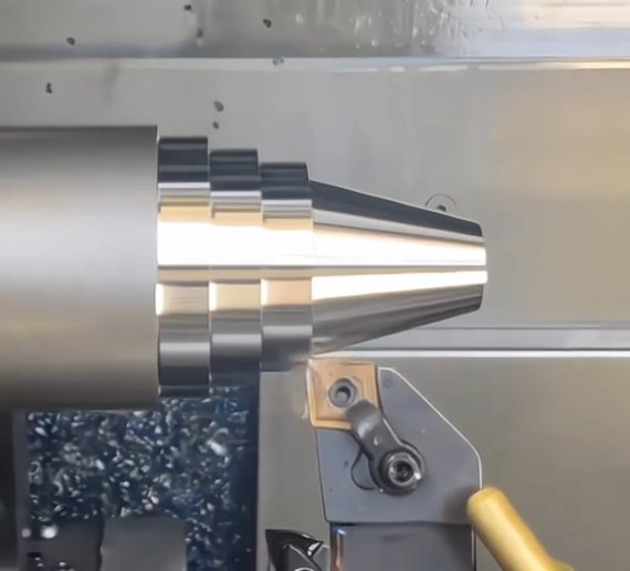
CNC lathe boring is used for round parts where the workpiece rotates and the boring bar remains stationary or moves along the axis. It is common for bushings, sleeves, valve bodies, bearing seats, pulleys, shafts with internal features, and threaded internal bores.
CNC Mill Boring
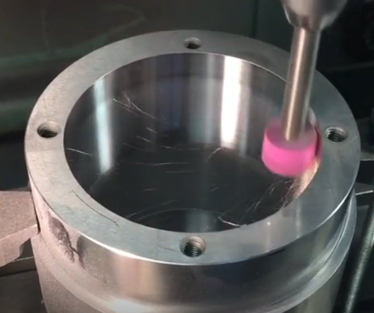
On a CNC machining center, the boring head or boring tool rotates while the workpiece remains fixed. This method is suitable for plates, blocks, housings, manifolds, brackets, and components requiring accurate hole position relative to other milled features.
Horizontal Boring Mill Machining
Horizontal boring mills are used for large and heavy components such as gearboxes, pump housings, turbine casings, mining equipment, and machine bases. They provide long travel, rigid spindle support, and the ability to machine large bores while maintaining alignment across wide distances.
Line Boring
Line boring restores or creates multiple bores along the same centerline. It is often used for excavator arms, loader frames, engine blocks, marine equipment, and hinge bores. Portable line boring can be performed in the field when removing the part would be expensive or impractical.
Jig Boring
Jig boring is selected when hole location accuracy is critical. It is associated with precision tooling, dies, fixtures, gauges, aerospace components, and parts requiring tight positional tolerances.
When is boring better than reaming?
Boring is usually better when the existing hole is not straight, not round, poorly located, or has significant stock variation. Reaming can produce a good finish and accurate size, but it follows the existing hole and has limited ability to correct position or alignment errors.
Metal Boring Tools and Tooling Choices
Tool selection has a direct effect on accuracy, cycle time, chip evacuation, and surface finish. The most common boring tools include solid boring bars, indexable boring bars, fine boring heads, twin-cutter boring heads, damped boring bars, and modular boring systems.
| Tool Type | Best Use | Key Consideration |
|---|---|---|
| Solid carbide boring bar | Small to medium bores requiring rigidity | Higher stiffness than steel at the same diameter |
| Indexable boring bar | General CNC boring and metal production machining | Insert grade and chipbreaker must match the metal |
| Fine boring head | Close-tolerance finishing | Micron-level diameter adjustment is possible on high-quality heads |
| Damped boring bar | Deep holes and long overhangs | Reduces chatter in high length-to-diameter ratios |
| Line boring bar | Coaxial bores and repair work | Requires accurate setup and support bearings |
A key rule is to keep tool overhang as short as possible. In internal machining, boring bars are less rigid than external turning tools because the bar must fit inside the hole. As overhang increases, deflection and vibration increase rapidly.
For many steel and cast iron applications, a steel boring bar is stable up to about 3:1 length-to-diameter ratio. Carbide bars often perform better up to about 5:1 or 6:1, while damped bars may be used for deeper bores where chatter control is essential.
Tolerances, Surface Finish, and Hole Quality
The achievable result depends on machine rigidity, setup, material, tool condition, tool overhang, thermal stability, and inspection method. In production machining, typical bored-hole tolerances may range from ±0.025 mm to ±0.005 mm for precision work, but the actual capability must be confirmed by the machine shop and part geometry.
For fits, drawings often reference ISO 286 tolerance grades such as H7, H8, or H9. For geometric control, engineers may specify GD&T requirements such as position, cylindricity, straightness, perpendicularity, parallelism, total runout, or concentricity where applicable.
| Quality Requirement | Why It Matters | Common Measurement Method |
|---|---|---|
| Diameter | Controls bearing, bushing, pin, and seal fit | Bore gauge, air gauge, CMM |
| Roundness | Prevents uneven load and leakage | Roundness tester, CMM, bore gauge comparison |
| Straightness | Ensures shaft or pin alignment | CMM, precision mandrel, bore mapping |
| Surface finish | Affects friction, sealing, lubrication, and fatigue | Surface roughness tester |
| Position | Controls assembly alignment | CMM, jig inspection, optical measurement |
Surface finish for bored metal holes commonly falls in the Ra 0.8 to 3.2 micrometer range for many industrial applications. Finer finishes may require a finishing pass, sharp inserts, optimized cutting parameters, honing, or roller burnishing.
Can metal boring achieve bearing-fit tolerances?
Yes, boring can produce bearing seats and bushing bores when the machine, tooling, setup, and inspection process are capable. For high-volume or very tight fits, manufacturers may combine boring with reaming, honing, grinding, or matched inspection procedures.
Cutting Parameters for Metal Boring
Cutting speed, feed rate, depth of cut, insert geometry, coolant delivery, and chip control must be selected for the work material. The goal is to maintain dimensional stability while avoiding chatter, built-up edge, poor chip evacuation, and tool deflection.
Typical parameter planning includes rough boring to remove stock efficiently, semi-finish boring to stabilize the hole, and finish boring to reach the final dimension. Leaving a consistent finishing allowance is important because uneven stock can push the tool away and produce taper or size variation.
| Material | Common Boring Concern | Practical Machining Note |
|---|---|---|
| Carbon steel | Chip control and heat | Use suitable chipbreaker geometry and coolant flow |
| Stainless steel | Work hardening and built-up edge | Maintain positive cutting action and avoid rubbing |
| Aluminum | Material adhesion on cutting edge | Use polished, sharp inserts and effective chip evacuation |
| Cast iron | Abrasive wear and dust | Use wear-resistant inserts and manage dry or mist conditions carefully |
| Titanium | Heat concentration and tool wear | Use rigid setup, sharp tools, and controlled speeds |
Coolant-through boring bars are valuable in deep holes because chips must exit through a confined space. Poor chip evacuation can scratch the bore, break inserts, create size variation, or cause sudden tool failure.
Real Engineering Issues in Metal Boring
Metal boring problems are often caused by setup and rigidity rather than the cutting tool alone. A purchasing team may see a quote for “boring,” but the shop must understand bore length, tolerance, material hardness, interrupted cuts, datum structure, and inspection expectations before selecting the right process.
Problem: Chatter in a Deep Steel Bore
A hydraulic cylinder component required a 62 mm internal bore through a 310 mm length in alloy steel. The original process used a standard steel boring bar with a long overhang. The bore met rough size requirements but showed visible chatter marks and a surface finish around Ra 4.8 micrometers, which was unsuitable for the sealing system.
The corrective approach used a carbide-reinforced damped boring bar, reduced overhang, a two-pass strategy, and higher-pressure coolant directed at the cutting edge. The finish improved to approximately Ra 1.6 micrometers, and diameter variation across the bore was reduced from about 0.045 mm to less than 0.015 mm during first-article inspection.
Problem: Misaligned Bores in a Welded Frame
A fabricated equipment frame had two pivot bores that were distorted after welding. Drilling and reaming could not correct the axis error. Portable line boring was used after stress relief and fixture alignment. The final result restored coaxial alignment within the assembly requirement and reduced premature bushing wear during field operation.
These examples show why boring accuracy is not only a tooling issue. It depends on process planning, stock condition, fixturing, machine stiffness, inspection strategy, and communication between design and manufacturing teams.
Why do bored holes become tapered?
Taper can result from tool deflection, worn inserts, thermal growth, excessive overhang, inconsistent stock allowance, spindle misalignment, or insufficient machine rigidity. A spring pass may help in some cases, but the root cause should be corrected rather than relying only on repeated passes.
How to Specify Metal Boring on Drawings and RFQs
Clear specifications reduce quoting uncertainty and production risk. Instead of requesting only “bore to size,” engineering and purchasing teams should provide enough detail for the machine shop to choose the correct boring method, tooling, and inspection plan.
- Final bore diameter and tolerance, including fit class if applicable
- Bore depth, through-hole or blind-hole condition, and bottom geometry
- Material grade, hardness, heat treatment, and coating condition
- Required surface finish, such as Ra value or functional sealing requirement
- GD&T controls, including position, straightness, cylindricity, or runout
- Datum references and critical mating components
- Production quantity, prototype quantity, and expected repeat orders
- Inspection report requirements, such as CMM report or first article inspection
- Allowance condition, such as cast hole, drilled pilot hole, or flame-cut opening
For buyers, the most important cost drivers are bore size, bore depth, tolerance, material machinability, setup complexity, inspection level, and whether special tooling is required. Deep precision bores are generally more expensive than shallow bores because they demand higher rigidity, better chip control, and slower finishing passes.
A good RFQ for CNC boring services should include a 2D drawing, 3D model if available, material specification, annual volume estimate, and any functional requirements such as bearing press fit, oil retention, seal contact, or shaft alignment.
Metal Boring Cost Drivers and Buyer Considerations
Metal boring cost is not based only on hole diameter. Two bores with the same nominal size can require very different machining time and inspection effort. A shallow clearance bore in aluminum may be simple, while a deep H7 bearing bore in stainless steel with tight positional tolerance may require multiple setups, fine boring, in-process gauging, and controlled thermal conditions.
| Cost Driver | Impact on Price | Engineering Recommendation |
|---|---|---|
| Tight diameter tolerance | More finishing passes and inspection | Specify tight tolerance only where function requires it |
| Long bore depth | Higher tooling cost and slower feed rates | Review whether full-depth precision is necessary |
| Difficult material | Higher tool wear and longer cycle time | Provide hardness and material certification |
| Interrupted cut | Greater vibration and insert wear | Allow process review before finalizing geometry |
| High inspection requirement | Additional metrology time | Define critical dimensions and reporting format clearly |
From a supplier evaluation perspective, buyers should ask whether the shop has suitable boring equipment, calibrated bore gauges, CMM capability, experience with the target material, and a documented process for first-article approval. For large parts, lifting capacity, machine travel, and fixture design can be just as important as spindle power.
Quality Control for Precision Metal Boring
Quality control begins before machining. The workpiece must be located from the correct datums, clamped without distortion, and allowed to stabilize if thermal effects are significant. During machining, operators may measure rough and semi-finished bores before taking the final pass.
Final inspection may use dial bore gauges, three-point internal micrometers, plug gauges, air gauges, surface roughness testers, CMMs, and roundness measuring equipment. For high-precision bores, inspection temperature and gauge calibration should be controlled to avoid false acceptance or rejection.
Important inspection records may include first-article inspection reports, material certificates, dimensional reports, surface finish readings, and capability data for production runs. In regulated industries, documentation may follow customer-specific quality systems or standards such as ISO 9001, AS9100, IATF 16949, or medical device quality requirements where applicable.
Metal Boring vs. Related Hole Finishing Processes
Boring is one of several processes used to produce accurate holes in metal. Choosing the correct process depends on whether the main requirement is location accuracy, diameter control, roundness, surface texture, productivity, or cost.
| Process | Strength | Limitation |
|---|---|---|
| Boring | Corrects hole size, geometry, and location | Can be slower than drilling or reaming |
| Reaming | Efficient finishing of prepared holes | Does not significantly correct location error |
| Honing | Excellent surface finish and roundness | Usually requires a pre-machined bore |
| Internal grinding | Very accurate hardened bores | Higher cost and longer cycle time |
| Broaching | Fast production of internal profiles | Requires dedicated tooling and suitable geometry |
In many manufacturing routes, boring is the critical step that establishes accurate geometry before a final finishing operation. For example, a hydraulic bore may be rough bored, semi-finish bored, honed, and then inspected for diameter, straightness, and surface texture.
Conclusion: When Metal Boring Is the Right Choice
Metal boring is the right machining process when an existing hole must be made more accurate, straighter, rounder, smoother, or better aligned with functional datums. It is especially valuable for bearing seats, bushing holes, precision housings, engine and gearbox components, hydraulic parts, and large fabricated structures.
For reliable results, engineers should define functional tolerances clearly, buyers should provide complete drawings and material data, and machinists should select tooling and parameters based on bore depth, material, rigidity, and inspection requirements. When these factors are aligned, precision metal boring can deliver stable dimensions, improved assembly performance, and longer service life for critical metal components.