Metal milling is a subtractive manufacturing process that removes material from a metal workpiece using rotating cutting tools. It is widely used to produce precision machined parts, prototypes, tooling, fixtures, molds, aerospace components, automotive parts, medical device components, electronics housings and industrial machine parts.
For engineers, sourcing teams and product buyers, the main search intent behind metal milling is usually practical: how the process works, which metals can be milled, what tolerances are realistic, how to reduce machining cost, and how to specify a part so it can be manufactured accurately and repeatably. This guide covers those points with an engineering and procurement perspective.
What Is Metal Milling?
Metal milling is a machining operation in which a rotating cutter removes chips from a stationary or moving workpiece. Unlike turning, where the workpiece rotates, milling normally uses a rotating tool and controlled linear or multi-axis motion to generate slots, pockets, flat faces, contours, holes, threads and complex 3D surfaces.
Modern milling is most often performed on CNC machining centers. CNC milling uses computer numerical control to move cutting tools along programmed toolpaths, enabling consistent dimensions, complex geometry and repeatable production from one prototype to thousands of parts.
Typical metal milling operations include face milling, end milling, slot milling, shoulder milling, profile milling, drilling, tapping, thread milling, chamfering, boring and 3D contour milling. The process can machine billet, plate, bar stock, castings, forgings and near-net-shape blanks.
How the Metal Milling Process Works
A metal milling project usually follows a controlled workflow from design review to final inspection. The details vary by shop, material and part complexity, but the typical process includes the following steps:
- CAD model review: The manufacturer checks part geometry, tolerances, datums, material requirements, surface finish and potential machining risks.
- DFM analysis: Engineers identify deep pockets, thin walls, inaccessible radii, tight tolerances, burr-prone edges and features that may increase cost.
- CAM programming: Toolpaths are generated for roughing, semi-finishing, finishing, drilling, tapping and deburring operations.
- Workholding setup: The part is clamped using a vise, fixture, soft jaws, vacuum plate, modular tooling or custom fixture.
- Tool selection: End mills, drills, inserts, reamers, taps, thread mills and chamfer tools are selected based on material and feature geometry.
- Machining: The machine removes material under controlled spindle speed, feed rate, depth of cut, coolant and tool engagement.
- Deburring and finishing: Edges are broken, burrs are removed and secondary finishes may be applied.
- Inspection: Critical dimensions are checked using calipers, micrometers, height gauges, CMM, optical systems, surface roughness testers or thread gauges.
For high-value components, process control may also include first article inspection, in-process probing, tool wear monitoring, statistical process control and full dimensional reports.
Common Types of Metal Milling Machines
The correct milling machine depends on part size, geometry, tolerances, production volume and the number of sides that need machining.
3-Axis CNC Milling
3-axis milling uses X, Y and Z linear motion. It is suitable for flat faces, holes, pockets, slots, simple contours, plates, brackets, covers and many general machined components. It is often cost-effective for parts that can be produced in one or two setups.
4-Axis CNC Milling
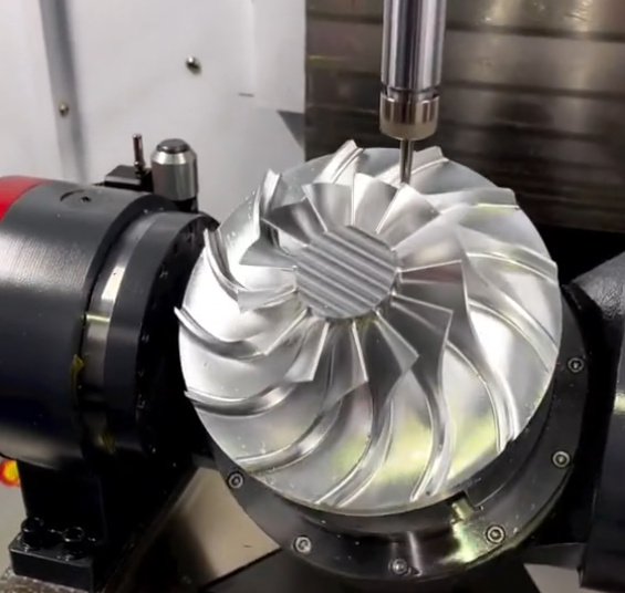
4-axis milling adds rotary movement, allowing features to be machined around a cylindrical or multi-sided part with fewer setups. It is useful for shafts with milled flats, parts with radial holes, valve bodies, impellers and components requiring indexed machining.
5-Axis CNC Milling
5-axis milling controls five motion axes, enabling complex contours, undercuts and angled features with reduced setup time. It is commonly used for aerospace structural parts, turbine components, orthopedic implants, complex molds and high-precision prototypes. Although hourly machine rates are higher, 5-axis machining can reduce total cost when it eliminates multiple fixtures and improves geometric accuracy.
Vertical and Horizontal Milling
Vertical machining centers are versatile and common for general CNC milled parts. Horizontal machining centers are often preferred for production machining, heavy material removal and parts requiring multiple sides because they offer excellent chip evacuation and can use pallet systems for higher throughput.
Metals Commonly Used in Milling
Material selection strongly affects machinability, cutting speed, tool wear, achievable surface finish and final part cost. The table below summarizes common materials used in precision metal milling.
| Material | Typical Grades | Machining Characteristics | Common Applications |
|---|---|---|---|
| Aluminum | 6061, 6082, 7075, 2024 | Excellent machinability, high cutting speeds, good surface finish, low weight | Housings, brackets, heat sinks, aerospace parts, prototypes |
| Stainless Steel | 304, 316, 17-4 PH, 420 | Work-hardening risk, requires rigid setup, good corrosion resistance | Medical parts, food equipment, marine components, valves |
| Carbon Steel | 1018, 1045, A36 | Good machinability, economical, often requires coating or plating for corrosion protection | Frames, shafts, fixtures, machine components |
| Alloy Steel | 4140, 4340, 8620 | High strength, can be heat treated, moderate to difficult machining depending on hardness | Gears, tooling, high-load mechanical parts |
| Titanium | Grade 2, Grade 5 Ti-6Al-4V | Low thermal conductivity, high tool wear, requires controlled cutting parameters | Aerospace, implants, high-performance fasteners |
| Brass and Copper | C360, C110, C101 | Brass machines easily; copper can be gummy and requires sharp tooling | Electrical parts, fittings, terminals, heat transfer components |
| Tool Steel | D2, A2, H13, O1 | Can be difficult after hardening; often rough machined before heat treatment | Molds, dies, punches, wear-resistant tooling |
Aluminum 6061 is often the default choice for cost-effective machined prototypes because it is stable, widely available and easy to finish. Stainless steel 316 is selected when corrosion resistance is important, while 7075 aluminum, titanium and alloy steels are used when strength-to-weight ratio or high mechanical performance matters.
Metal Milling Tolerances and Surface Finishes
Precision expectations must be defined clearly because tolerances affect setup strategy, inspection method, machining time and scrap risk. General CNC milled metal parts are often produced to tolerances around ±0.005 in or ±0.13 mm when no tighter requirements are specified. Precision features can often be held to ±0.001 in or ±0.025 mm, and specialized processes may achieve tighter values under controlled conditions.
Tight tolerances should be applied only where function requires them, such as bearing fits, sealing surfaces, locating datums, dowel holes and mating interfaces. Applying tight tolerances to every dimension increases inspection time and machining cost without improving part performance.
| Requirement | Typical Range | Engineering Notes |
|---|---|---|
| General linear tolerance | ±0.005 in / ±0.13 mm | Common for non-critical milled features |
| Precision milled feature | ±0.001 to ±0.002 in / ±0.025 to ±0.05 mm | Requires stable workholding, sharp tools and inspection control |
| Reamed hole | Often within ±0.0005 to ±0.001 in | Depends on material, hole depth, tool condition and setup rigidity |
| Standard milled surface finish | Ra 1.6 to 3.2 μm | Suitable for many mechanical components |
| Fine machined finish | Ra 0.8 μm or better | May require finishing pass, optimized tooling or secondary processing |
Surface finish depends on feed per tooth, tool runout, toolpath strategy, cutter geometry, material hardness, coolant and machine rigidity. A part that looks visually smooth may still fail a specified Ra requirement, so roughness should be called out only where it is functionally needed.
When should a buyer request a CMM inspection report?
A coordinate measuring machine report is useful for parts with critical datums, tight geometric tolerances, mating assemblies, aerospace or medical requirements, first article approval, or supplier qualification. For simple brackets or non-critical prototypes, a standard inspection report may be sufficient.
Key Cutting Parameters in Metal Milling
Machining performance depends on the relationship between cutting speed, spindle speed, feed rate, chip load, radial engagement, axial depth of cut and coolant strategy. These parameters are selected to balance productivity, tool life, dimensional accuracy and surface quality.
- Cutting speed: The surface speed between cutter and workpiece, typically expressed in meters per minute or surface feet per minute.
- Spindle speed: The tool rotation speed, calculated from cutting speed and tool diameter.
- Feed rate: The linear movement rate of the tool relative to the part.
- Chip load: The material thickness removed by each cutting edge per revolution.
- Depth of cut: The axial or radial amount of material removed in a pass.
- Coolant or lubrication: Used to control heat, evacuate chips and improve tool life.
For example, aluminum can often be machined at high spindle speeds and aggressive feed rates because it conducts heat well and forms chips easily. Titanium requires lower cutting speeds, high-pressure coolant and careful tool engagement because heat concentrates near the cutting edge, accelerating tool wear.
Tool life is especially important in production milling. A small change in tool wear can alter part dimensions, surface finish and burr formation. For high-volume work, manufacturers may use tool life limits, sister tools, in-machine probing and offset compensation to keep production stable.
Design for Manufacturability in Metal Milling
Good design for manufacturability reduces machining time, improves quality and lowers part cost. Many milling cost issues are created in the CAD model before a supplier ever quotes the job.
Use Practical Internal Radii
Because milling cutters are round, internal corners cannot be perfectly sharp. Designing internal corner radii larger than the cutter radius improves tool access and reduces machining time. A pocket with a 3 mm internal radius is generally easier and cheaper to machine than the same pocket with a 0.5 mm radius.
Avoid Unnecessarily Deep Pockets
Deep pockets require long tools, which increase vibration and reduce rigidity. As a rule of thumb, pocket depth greater than 4 to 6 times the tool diameter may require slower machining, special tooling or multiple operations.
Control Thin Walls
Thin walls can deflect during cutting, especially in aluminum, stainless steel and titanium. If a wall is too thin relative to its height, the part may chatter, warp or fail inspection. Adding ribs, increasing wall thickness or allowing stress-relief operations can improve results.
Specify Threads and Holes Clearly
Thread type, depth, class of fit and whether a hole is blind or through should be clearly marked on the drawing. For deep threaded holes, thread milling may provide better control than tapping, particularly in hard metals or expensive parts where broken taps are high risk.
Limit Cosmetic Requirements to Visible Areas
Uniform cosmetic finishing on all surfaces increases handling and inspection effort. If only external surfaces are visible in the final product, define cosmetic requirements only for those areas and allow standard machined finish elsewhere.
Practical DFM checklist before sending a milling RFQ
- Provide both 3D CAD and 2D drawings for critical dimensions.
- Identify critical-to-function features rather than tightening all tolerances.
- Use standard material grades and stock sizes where possible.
- Confirm surface finish, coating, heat treatment and inspection requirements.
- Check that internal corner radii match available cutter sizes.
- Avoid very deep, narrow slots unless functionally required.
- Define datum structure for parts with geometric tolerances.
Cost Drivers in Metal Milling
Metal milling cost is influenced by more than machine time. Buyers often compare quotes by unit price, but the technical reasons behind price differences are important for quality and delivery risk.
| Cost Driver | Why It Matters | How to Reduce Cost |
|---|---|---|
| Material type | Titanium, stainless steel and hardened steels increase tool wear and cycle time | Use machinable grades when performance allows |
| Material removal volume | Parts cut from oversized billets require more roughing time | Choose near-net stock, extrusion, casting or forging for high-volume parts |
| Setup count | Each setup adds labor, fixturing and alignment risk | Design features to be machined from fewer orientations |
| Tolerance requirements | Tighter tolerances require slower finishing, stable temperature and more inspection | Apply tight tolerances only to functional interfaces |
| Surface finish | Fine finishes require additional passes or secondary finishing | Separate cosmetic surfaces from non-critical internal areas |
| Batch size | Programming and setup costs are spread over fewer or more units | Order economic batch quantities when design is stable |
| Inspection level | CMM reports and full dimensional inspection add quality control time | Define inspection level by risk and application |
Unit cost typically decreases when production quantity increases because CAM programming, fixture preparation and setup time are distributed across more parts. However, if a part requires slow machining due to difficult material or tight tolerance, the minimum achievable cost may still be limited by cycle time and tool consumption.
Real Engineering Example: Reducing Cycle Time and Scrap
A common production issue in metal milling is chatter and dimensional drift in thin-walled aluminum housings. Consider a 6061-T6 electronics enclosure with 2.0 mm walls, a 38 mm deep pocket and a flatness requirement of 0.08 mm on the mounting face. The first machining plan used aggressive roughing, minimal support under the floor and a finishing pass after most material had been removed.
The result was wall vibration, visible tool marks and a scrap rate near 9% due to flatness and cosmetic defects. After process review, the machining strategy was changed:
- Roughing was split into staged pocketing to leave temporary support material.
- Finishing passes were delayed until thermal and mechanical stress were reduced.
- A larger internal corner radius was approved, allowing a more rigid cutter.
- Soft jaws were modified to support the thin side walls more evenly.
- Final inspection added in-process probing before the last finishing operation.
The revised process reduced average cycle time from 18.5 minutes to 15.2 minutes per part, a reduction of about 18%. Scrap decreased from 9% to below 2%, and the measured flatness range improved from 0.06-0.14 mm to 0.03-0.07 mm. This type of improvement is typical when part design, fixturing and toolpath strategy are reviewed together instead of treating machining as a purely programming task.
Metal Milling vs. Other Manufacturing Processes
Milling is not always the best manufacturing method. It should be compared with turning, sheet metal fabrication, casting, forging, extrusion, laser cutting, EDM and additive manufacturing depending on geometry, quantity and performance requirements.
| Process | Best For | Limitations Compared with Milling |
|---|---|---|
| CNC Turning | Round parts, shafts, bushings, threaded components | Less suitable for prismatic features unless live tooling is used |
| Sheet Metal Fabrication | Brackets, panels, enclosures made from sheet | Limited thickness, bend radius and 3D machined features |
| Casting | Complex shapes at medium to high volume | Tooling cost, porosity risk and post-machining often required |
| Forging | High-strength parts with favorable grain flow | High tooling cost and limited design flexibility for low volume |
| EDM | Hard metals, sharp internal corners, deep narrow features | Slower material removal and limited to conductive materials |
| Metal 3D Printing | Internal channels, lightweight lattices, complex prototypes | Higher material cost, rougher surface and post-machining often needed |
Milling is especially strong when parts require accurate flat surfaces, precise holes, controlled datums, machined pockets and repeatable mechanical interfaces. In many production projects, the best solution is hybrid: casting or forging creates the rough shape, and CNC milling finishes critical surfaces.
Quality Control and Inspection for Milled Metal Parts
Quality control in milling should match the application risk. A simple fixture plate may only need basic dimensional checks, while an aerospace bracket or medical implant may require traceable material certificates, first article inspection, CMM reports and documented process control.
Inspection planning should be considered before production starts. If datums are unclear or drawings conflict with the CAD model, suppliers may inspect the part differently than the buyer expects. Clear datum references, geometric dimensioning and tolerancing, and acceptance criteria reduce disputes and rework.
- Incoming material verification: Confirms material grade, certificate and heat lot where required.
- First article inspection: Validates the first production part before batch machining continues.
- In-process inspection: Checks critical features during production to detect drift early.
- Final inspection: Confirms dimensions, surface finish, threads, burrs and cosmetic requirements.
- Traceability: Links parts to material certificates, inspection records and production batches.
Common inspection tools used for CNC milled metal parts
Calipers, micrometers, bore gauges, pin gauges, thread gauges, height gauges, optical comparators, coordinate measuring machines, surface roughness testers, hardness testers and in-machine probes are commonly used. The correct tool depends on tolerance, feature type and documentation requirements.
Buyer and Engineer Considerations Before Ordering Metal Milling
From a procurement perspective, the lowest quote is not always the best value. Metal milling requires correct material sourcing, experienced programming, stable workholding, reliable inspection and realistic delivery planning. A quote that ignores difficult tolerances, secondary finishing or inspection requirements may lead to delays or nonconforming parts.
Before placing an order, buyers and engineers should evaluate whether the supplier can handle the required material, machine envelope, tolerance class, finish, volume and documentation. For critical components, it is reasonable to ask about machine capability, inspection equipment, material traceability, previous experience with similar parts and quality management practices.
Useful RFQ information includes:
- 3D CAD file in STEP, Parasolid or native CAD format
- 2D drawing with critical dimensions, tolerances and datums
- Material grade, temper, hardness and any certification requirement
- Quantity, prototype or production status, and expected annual volume
- Surface finish, anodizing, plating, passivation, heat treatment or coating requirements
- Inspection requirements such as standard report, CMM report or first article inspection
- Functional notes for sealing, sliding, bearing, assembly or cosmetic surfaces
Secondary Operations After Metal Milling
Many milled metal parts require secondary operations to achieve final performance, appearance or assembly requirements. These processes should be specified early because they can affect dimensions and tolerances.
| Secondary Operation | Purpose | Important Consideration |
|---|---|---|
| Anodizing | Improves corrosion resistance and appearance of aluminum | Build-up affects dimensions; masking may be required |
| Passivation | Improves corrosion resistance of stainless steel | Requires proper cleaning and compatible stainless grades |
| Plating | Adds corrosion resistance, wear resistance or conductivity | Thickness must be considered on precision fits |
| Heat Treatment | Changes hardness, strength or wear resistance | Can cause distortion; machining sequence matters |
| Grinding | Achieves high precision and fine surface finish | Often used for critical flatness or tight fits |
| Deburring | Removes sharp edges and loose burrs | Edge break size should be defined for functional parts |
| Laser Marking | Adds serial numbers, logos or traceability marks | Mark location and depth should not affect functional surfaces |
For coated or plated parts, the drawing should clarify whether dimensions apply before or after finishing. This is especially important for holes, grooves, sealing surfaces and sliding fits.
Conclusion: When Metal Milling Is the Right Choice
Metal milling is one of the most versatile and reliable processes for producing accurate metal components. It is suitable for prototypes, low-volume production, precision fixtures and high-value end-use parts that require tight control of geometry, surface quality and material performance.
The best milling results come from aligning design, material, tolerances, machining strategy, workholding and inspection requirements. Engineers can reduce cost by using practical radii, avoiding unnecessary tight tolerances, simplifying setups and specifying finishes only where needed. Buyers can reduce sourcing risk by providing complete technical data and evaluating suppliers based on capability, not price alone.
When properly specified and manufactured, CNC metal milling delivers repeatable precision, strong material properties and production flexibility across industries ranging from aerospace and medical devices to robotics, electronics, energy and industrial equipment.