
Bushing machining services
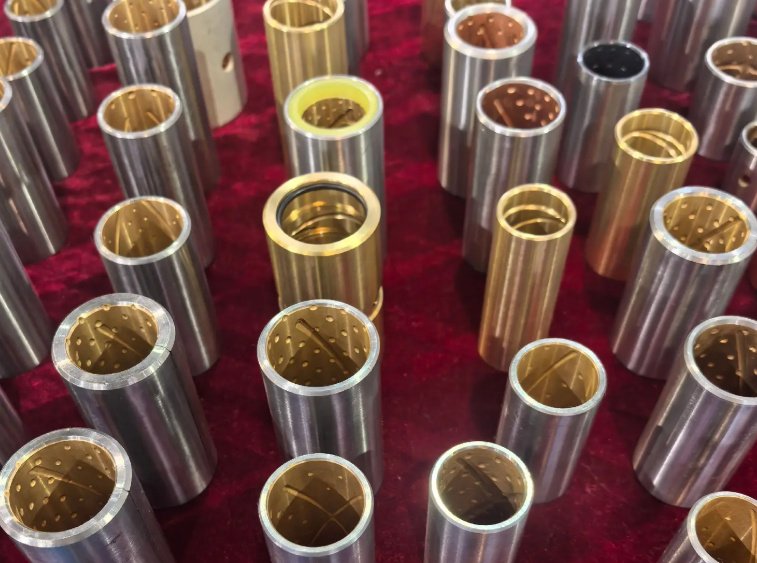
Bushing machining services support the production of precision sleeve bearings, plain bearings, flanged bushings, spacer bushings, wear bushings and custom bearing liners used in industrial equipment, automotive systems, hydraulic assemblies, agricultural machinery, mining equipment, robotics and aerospace support components.
Whether the requirement is a single replacement bushing, a prototype run, or repeat production, the machining process must control bore size, outside diameter, wall thickness, concentricity, surface finish and material compatibility. A well-machined bushing reduces shaft wear, improves alignment, supports lubrication, and extends service life in rotating, oscillating or sliding applications.
Our bushing machining approach focuses on fit, friction control, load capacity and repeatable dimensional accuracy, helping engineers and buyers source parts that install correctly and perform reliably in real equipment conditions.
Custom Bushing Machining for Sleeve Bearings, Flanges and Wear Components
Custom bushings are often specified when standard catalog parts do not match the shaft size, housing bore, operating clearance, lubrication method or load condition. Machining allows the bushing geometry, material and finish to be tailored to the assembly instead of forcing the assembly to adapt to an off-the-shelf component.
Common machined bushing features include:
- Precision inside diameter for shaft fit and running clearance
- Controlled outside diameter for press fit, slip fit or thermal installation
- Flanged ends for axial location and thrust support
- Oil grooves, grease grooves, spiral grooves and lubrication holes
- Chamfers and lead-in radii to prevent installation damage
- Cross holes, slots, notches, flats and anti-rotation features
- Counterbores, shoulders and stepped profiles
- Honed, reamed, bored or ground bearing surfaces
| Feature | Machining Method | Engineering Purpose |
|---|---|---|
| Inside diameter | Boring, reaming, honing, internal grinding | Controls shaft clearance, friction and alignment |
| Outside diameter | CNC turning, grinding | Controls housing fit and retention |
| Flange face | Facing, turning, grinding | Supports thrust load and axial location |
| Lubrication groove | Grooving, milling, form tooling | Improves grease or oil distribution |
| Mounting hole | Drilling, cross drilling, deburring | Allows oil feed, pinning or assembly alignment |
Bushing Types We Machine
Different bushing types solve different bearing, spacing and wear-control problems. The correct design depends on shaft motion, radial load, axial load, temperature, contamination level, installation method and maintenance expectations.
- Sleeve bushings: Cylindrical plain bearings used for radial support around a shaft or pin.
- Flanged bushings: Sleeve bushings with an integral flange for axial positioning or thrust control.
- Thrust bushings: Components designed to handle axial loading and reduce face wear.
- Spacer bushings: Precision distance pieces used to maintain alignment or assembly spacing.
- Wear bushings: Replaceable sacrificial components used to protect expensive housings or shafts.
- Guide bushings: Components used to guide pins, rods, shafts or tooling elements.
- Split bushings: Bushings with a machined split for easier installation or compression fit.
- Custom bearing liners: Machined liners for housings, cylinders, pivots and heavy equipment joints.
For replacement projects, reverse engineering can be used when drawings are unavailable. Critical dimensions such as ID, OD, length, flange thickness, groove position and wear pattern should be measured before final machining.
Materials for Precision Bushing Machining
Material selection has a direct effect on wear resistance, galling behavior, load capacity, machinability, corrosion resistance and lubrication requirements. A bushing that machines well is not always the best material for the application; the final choice should consider both manufacturing efficiency and operating environment.
| Material | Typical Use | Key Considerations |
|---|---|---|
| SAE 660 / C93200 bearing bronze | General-purpose sleeve bearings, hydraulic pivots, industrial machinery | Excellent machinability, good wear resistance, compatible with lubrication grooves |
| Aluminum bronze | High-load bushings, marine hardware, heavy equipment | Higher strength than standard bearing bronze, more demanding to machine |
| Manganese bronze | Heavy-duty bushings, impact and shock-load applications | Good strength, used where toughness is important |
| Oil-impregnated bronze | Low-maintenance sleeve bearings and small mechanical assemblies | Porosity must be protected; aggressive machining can affect oil retention |
| Carbon steel and alloy steel | Spacer bushings, hardened wear sleeves, structural applications | Can be heat treated, plated or ground for improved wear life |
| Stainless steel | Corrosive environments, food processing, marine and chemical equipment | Requires proper tooling to control work hardening and surface finish |
| PTFE, PEEK, acetal and nylon | Low-friction, lightweight or non-metallic bearing applications | Thermal expansion and moisture absorption must be considered |
| Composite bearing materials | Self-lubricating and maintenance-reduced applications | Machining method depends on backing material and bearing layer thickness |
Material selection note for buyers and engineers
Bronze is often selected for metal plain bearings because it offers a favorable balance of machinability, embeddability and wear resistance. Steel may be preferred where structural strength or hardening is needed. Engineering plastics can reduce weight and friction, but they require careful allowance for thermal growth, creep and water absorption.
CNC Bushing Machining Capabilities
Precision bushing manufacturing typically combines CNC turning with secondary operations such as drilling, milling, broaching, honing, grinding, deburring and inspection. The sequence depends on wall thickness, material, feature complexity and tolerance requirements.
Typical machining capabilities include:
- CNC turning for OD, ID, shoulders, grooves and flanges
- Internal boring for controlled bearing bores
- Reaming for repeatable hole sizing and improved finish
- Honing for tighter bore geometry and smoother bearing surfaces
- Centerless grinding or cylindrical grinding for precise OD control
- Cross drilling for grease holes, oil feed holes and retaining pins
- Broaching or milling for keyways, flats and anti-rotation features
- Chamfering and deburring to improve assembly safety
- Part marking, batch traceability and packaging protection
| Dimension or Feature | Typical Range | Notes |
|---|---|---|
| ID tolerance | ±0.0005 in to ±0.002 in / ±0.013 mm to ±0.05 mm | Application dependent; honing or grinding may be required for tighter bores |
| OD tolerance | ±0.0005 in to ±0.003 in / ±0.013 mm to ±0.08 mm | Press-fit bushings usually require tighter OD control |
| Concentricity | 0.001 in to 0.003 in / 0.025 mm to 0.08 mm | Depends on setup, length-to-diameter ratio and material stability |
| Surface finish | 16 to 63 µin Ra / 0.4 to 1.6 µm Ra | Bearing surfaces may need smoother finishes for low-friction operation |
| Length tolerance | ±0.001 in to ±0.005 in / ±0.025 mm to ±0.13 mm | Flanged and thrust applications may require tighter face control |
These values are representative rather than universal. Final tolerance selection should be based on function, inspection method, production volume and cost target. Over-tolerancing a non-critical spacer bushing can increase cost without improving performance, while under-tolerancing a press-fit bearing can create installation failure.
Engineering Controls for Fits, Clearances and Surface Finish
Bushing performance depends heavily on the relationship between the shaft, bushing bore and housing. A bushing can meet the drawing dimensions but still fail if the fits are not designed around load, heat, lubrication and installation method.
Important engineering controls include running clearance, interference fit, bore roundness, surface roughness and edge condition. These factors influence friction, heat generation, seizure risk and wear pattern development.
- Running clearance: Too little clearance can cause seizure after thermal expansion; too much clearance can cause vibration, edge loading and accelerated wear.
- Press fit: Excessive interference can collapse the bore after installation; insufficient interference may allow the bushing to spin in the housing.
- Surface finish: A bearing bore that is too rough can wear the shaft; a surface that is too smooth may reduce lubricant retention in some applications.
- Concentricity: Poor alignment between ID and OD can create uneven loading and localized wear.
- Chamfers: Proper lead-in chamfers reduce shaving, galling and edge damage during assembly.
Press-fit bushing issue: why the bore changes after installation
When a bushing is pressed into a housing, the outside diameter compresses and the inside diameter may shrink. For thin-wall bushings, this effect can be significant. In many engineered assemblies, the bushing is machined slightly oversize on the ID before installation and then finish-reamed or honed after pressing to achieve the final running clearance.
Machining Process for Custom Bushings
A controlled bushing machining workflow reduces dimensional variation and prevents quality issues such as tapered bores, burrs in lubrication holes, out-of-round thin walls and poor flange squareness.
- Drawing and requirement review: Confirm material, tolerances, quantity, surface finish, fit class, heat treatment, plating and inspection requirements.
- Material preparation: Select certified bar, tube, casting or plate stock suitable for the bushing geometry and operating conditions.
- Rough machining: Remove material while leaving stock for finish cuts, especially for longer bushings or stress-sensitive materials.
- Finish turning and boring: Establish final OD, ID, face length, flange diameter and shoulders.
- Secondary features: Machine oil grooves, grease holes, flats, notches, cross holes, slots or keyways.
- Deburring and edge finishing: Remove burrs from bores, grooves and holes that could damage shafts or contaminate lubrication systems.
- Inspection: Verify critical dimensions with calibrated gauges, micrometers, bore gauges, CMM, optical comparators or surface finish instruments.
- Cleaning and packaging: Protect finished bearing surfaces from chips, corrosion, moisture and transit damage.
When finish machining after heat treatment is recommended
If a steel wear bushing is carburized, induction hardened, through hardened or nitrided, dimensional movement may occur during thermal processing. In these cases, grinding, honing or final boring after heat treatment can improve bore accuracy, roundness and surface finish.
Applications for Machined Bushings
Machined bushings are used wherever motion, alignment, wear resistance or replaceable bearing surfaces are required. They are common in both high-volume machinery and one-off repair projects.
- Hydraulic cylinder pivots and pin joints
- Excavator, loader, bulldozer and crane linkage systems
- Agricultural implement pivots and hinge points
- Pumps, valves, compressors and rotating equipment
- Industrial conveyor systems and material handling machinery
- Automotive suspension, steering and drivetrain support components
- Marine shaft support and corrosion-resistant bearing applications
- Food processing and packaging machinery
- Robotics, automation fixtures and guide assemblies
- Tooling, molds, dies and precision guide posts
In heavy equipment repair, replacing a worn bushing is often far less expensive than replacing the mating housing or structural linkage. For this reason, wear bushings are commonly designed as serviceable components with controlled sacrificial wear behavior.
Real Engineering Problems Solved by Better Bushing Machining
Many bushing failures are not caused by material choice alone. They often result from tolerance stack-up, poor lubrication distribution, improper press fit, misalignment or burrs left after secondary machining.
| Problem | Likely Cause | Machining or Design Response |
|---|---|---|
| Bushing seizes on shaft | Insufficient clearance, thermal expansion, poor lubrication | Adjust bore size, improve surface finish, add lubrication grooves |
| Bushing rotates in housing | Insufficient press fit or housing wear | Increase OD interference, add anti-rotation feature, repair housing bore |
| Uneven wear on one side | Misalignment, poor concentricity, edge loading | Improve ID-to-OD concentricity, add chamfers, check shaft alignment |
| Rapid shaft wear | Bore too rough, wrong material pairing, embedded chips | Improve bore finish, deburr oil holes, clean and package parts properly |
| Cracking during installation | Excessive interference, sharp edges, brittle material | Revise press fit, add lead-in chamfer, review material condition |
Example: In a pivot assembly using a bronze sleeve bushing, changing from a straight bore to a machined grease groove with two cross-drilled feed holes can improve lubricant distribution across the loaded zone. In field service, this type of change commonly reduces dry-start scoring and extends maintenance intervals when the root cause is lubricant starvation.
For high-load bushings, improving concentricity from approximately 0.004 in to 0.0015 in and reducing bore roughness from about 125 µin Ra to 32 µin Ra can significantly improve contact uniformity. Actual life improvement depends on load, lubrication, contamination and shaft hardness, but the machining improvement directly addresses measurable wear drivers.
Information Needed to Quote or Specify a Machined Bushing
Clear technical information reduces back-and-forth communication, avoids incorrect assumptions and helps align cost with functional requirements. Buyers, maintenance teams and engineers should provide as much of the following information as possible.
- Part drawing, CAD model or sample part
- Material grade or performance requirement
- Inside diameter, outside diameter, length and flange dimensions
- Critical tolerances and non-critical dimensions
- Required fit: press fit, slip fit, transition fit or post-installation machining
- Shaft diameter, shaft material and shaft surface finish if known
- Housing bore size and material
- Load direction, speed, motion type and operating temperature
- Lubrication method: grease, oil, dry running or self-lubricating material
- Quantity, production frequency and delivery target
- Inspection documentation requirements
- Heat treatment, coating, plating or special cleaning requirements
If a worn sample is being used for reverse engineering, the original dimensions may not be obvious. Wear patterns, ovality and scoring should be evaluated so the replacement bushing is not copied from a failed condition.
Quality Documentation and Inspection for Bushing Machining
Bushing inspection should focus on the dimensions and characteristics that affect performance. For many parts, the most important measurements are ID, OD, roundness, concentricity, length, flange thickness, groove location and surface finish.
Available documentation may include:
- Material certificates or mill test reports
- First article inspection reports
- Dimensional inspection reports
- Surface finish readings
- Hardness test results for heat-treated parts
- Plating or coating certificates
- Batch traceability records
- Certificate of conformance
For production bushings, inspection planning should match the risk level of the application. A safety-critical linkage, hydraulic pivot or high-speed rotating assembly may require more detailed verification than a simple spacer bushing.
Design for Manufacturability Tips for Bushings
A manufacturable bushing design balances performance, inspection feasibility and machining cost. Small design changes can reduce cycle time, tool wear and scrap while improving installation reliability.
- Avoid unnecessarily tight tolerances on non-functional dimensions.
- Specify whether tolerances apply before or after pressing into the housing.
- Use practical chamfers on both ID and OD edges.
- Define lubrication groove width, depth and location clearly.
- Consider material availability in bar, tube or casting form to reduce waste.
- Use consistent wall thickness where possible to reduce distortion.
- Indicate inspection datums for concentricity and flange squareness.
- Specify surface finish only where it affects bearing performance.
- Allow finish honing or reaming when very tight ID control is required.
For procurement teams, the lowest unit price is not always the lowest installed cost. A bushing that requires hand fitting, causes assembly delays or fails early can create more cost than a slightly higher-priced part with better dimensional control and documentation.
Precision Bushing Machining for Prototype, Repair and Production Needs
Bushing machining services are valuable for new product development, equipment repair, production replacement parts and performance upgrades. The best results come from matching the material, tolerance, surface finish and lubrication features to the actual operating conditions.
A high-quality machined bushing should install without damage, maintain the intended shaft clearance, support the load path, distribute lubrication and wear predictably over its service life. By controlling the machining process and verifying critical dimensions, custom bushings can improve equipment reliability and reduce unplanned downtime.