
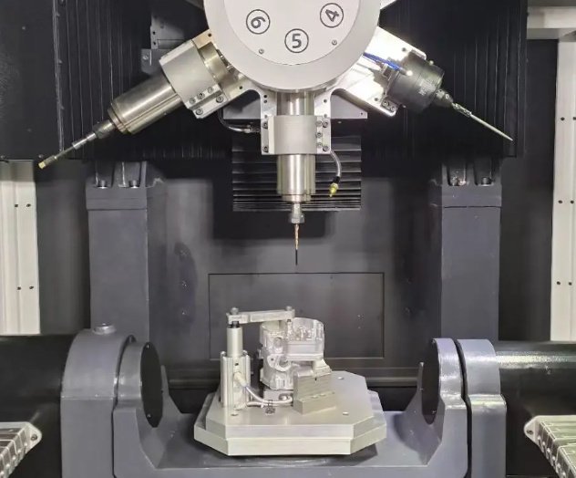
Metal deburring is the controlled removal of burrs, sharp edges, micro-projections and loose material left after machining, cutting, stamping, casting, forging or additive manufacturing. In production environments, metal deburring is not only a cosmetic finishing step; it directly affects assembly reliability, sealing performance, fatigue life, worker safety, coating adhesion and dimensional repeatability.
The right deburring process depends on material, burr size, part geometry, edge-break requirement, tolerance, annual volume, surface finish target and downstream use. A burr on a hydraulic manifold, aerospace bracket, medical implant, automotive gear or sheet metal enclosure can create very different risks, so the process must be selected around function rather than appearance alone.
What Is a Burr in Metalworking?
A burr is an unwanted raised edge or attached fragment of metal formed when material plastically deforms, tears or fractures during manufacturing. Burrs commonly appear after milling, drilling, turning, broaching, grinding, laser cutting, plasma cutting, waterjet cutting, blanking, punching and sawing.
Common burr types
- Poisson burr: caused by sideward material flow under compressive cutting forces.
- Rollover burr: formed when material bends rather than shears cleanly at an exit edge.
- Tear burr: created by ductile fracture or tearing during cutting.
- Cut-off burr: left when the final connection between part and stock separates.
- Thermal dross: resolidified metal from laser, plasma or flame cutting, often treated as a heavy burr condition.
- Micro-burr: small raised material often measured in microns, critical in precision valves, gears, implants and electronic components.
Engineering note: why burrs are difficult to standardize
Burr height, root thickness and attachment strength can vary along the same edge because tool wear, feed rate, exit angle, material hardness and grain direction change during production. A deburring specification should therefore define the acceptable edge condition, not just state “remove burrs.”
Why Metal Deburring Matters
Burrs are small defects that can create large downstream costs. In functional parts, a burr may break loose and contaminate an oil circuit, scratch a mating surface, prevent full seating, damage an O-ring, distort torque readings or initiate a fatigue crack. In handling and assembly, sharp edges increase injury risk and slow manual operations.
For many manufacturers, deburring and edge finishing are part of process capability, not rework. A consistent edge radius, chamfer or blended surface helps maintain stable assembly force, coating thickness and corrosion resistance.
Typical quality risks caused by poor deburring
- Leakage in hydraulic, pneumatic and fuel systems due to damaged seals or blocked ports.
- Electrical shorts or insulation damage in stamped metal electronic parts.
- Reduced fatigue strength from sharp notches and crack initiation sites.
- Paint, powder coating or anodizing defects around ragged edges.
- Part misalignment in precision assemblies due to raised material at mating faces.
- Excessive cleaning cost when loose chips and burr fragments remain inside passages.
Major Metal Deburring Methods
No single method is best for every metal part. Manual tools offer flexibility, tumbling offers batch efficiency, abrasive belts handle flat sheet and plate, while electrochemical and thermal deburring reach internal intersections that mechanical tools cannot access.
| Deburring method | Best suited for | Key advantages | Important limitations |
|---|---|---|---|
| Manual deburring | Low volume, prototypes, complex visible edges | Flexible, low equipment cost, fast setup | Operator variation, labor intensive, inconsistent edge radius |
| Vibratory tumbling | Small to medium metal parts in batches | Good for uniform edge break and surface smoothing | Not ideal for deep internal burrs or parts that can nest |
| Centrifugal barrel finishing | Small precision parts requiring faster cycle times | Higher energy than vibratory finishing, good repeatability | Fixture or media selection is critical to avoid damage |
| Abrasive belt or brush deburring | Laser-cut, punched, machined and sheet metal parts | Efficient for flat surfaces, edge rounding and oxide removal | May not reach complex internal geometry |
| Thermal energy deburring | Internal burrs in manifolds, valve bodies and precision machined parts | Removes inaccessible burrs quickly | Requires compatible materials, post-cleaning and process validation |
| Electrochemical deburring | Conductive metals with critical internal intersections | Non-contact, no mechanical stress, precise localized removal | Requires tooling, electrolyte control and conductive workpieces |
| Abrasive flow machining | Internal passages, cross holes and complex channels | Polishes and deburrs difficult internal features | Higher process cost, requires control of media viscosity and flow path |
| Robotic deburring | Repeatable medium to high volume parts | Stable cycle time, improved safety, programmable force control | Requires fixturing, programming and burr variation management |
Process note: deburring versus edge rounding
Deburring removes unwanted material. Edge rounding intentionally creates a measurable radius, often to improve coating coverage, reduce stress concentration or meet handling safety requirements. A part can be burr-free but still have an edge that is too sharp for its application.
Manual Metal Deburring
Manual deburring uses hand tools such as scrapers, files, countersinks, abrasive pads, rotary tools, carbide blades, mounted points and pneumatic grinders. It is common for prototypes, repair work, toolroom parts and features that automated equipment cannot reach economically.
Manual methods are effective when burrs are visible and accessible, but they depend heavily on operator skill. Over-deburring can change dimensions, break sharp functional edges or create uneven chamfers. Under-deburring leaves hidden fragments that may fail in service.
Best practices for manual deburring
- Use magnification or borescopes for critical holes, cross-drilled passages and small slots.
- Match tool hardness and cutting geometry to the material; stainless steel and titanium often need sharper, more controlled tools.
- Define acceptable edge break, such as 0.05 mm to 0.20 mm, instead of relying on subjective terms.
- Use go/no-go visual standards or sample parts to reduce operator-to-operator variation.
- Protect datum faces, threads and sealing surfaces from accidental rounding.
Mechanical and Mass Finishing Deburring
Mechanical deburring uses abrasive contact, impact, rubbing or cutting action to remove burrs. It includes vibratory finishing, barrel tumbling, centrifugal disc finishing, abrasive brushing, wide-belt sanding, planetary brush machines and magnetic pin finishing.
In medium and high-volume production, mechanical finishing can reduce labor cost and improve consistency. When the part geometry and media are matched correctly, a batch process can remove light burrs, blend tool marks and improve surface finish in one operation.
Media selection factors
- Ceramic media: aggressive cutting action for steel, stainless steel and hard alloys.
- Plastic media: gentler cutting for aluminum, brass, zinc and softer metals.
- Steel media: burnishing and brightening rather than heavy burr removal.
- Organic media: drying, polishing or fine finishing applications.
- Abrasive brushes: useful for sheet metal edges, drilled holes and machined surfaces.
For stamped or laser-cut parts, brush and belt deburring machines can remove vertical burrs, slag and oxide while creating a controlled edge radius. Typical production targets for powder-coated sheet metal often include a smooth edge radius to improve paint wrap and reduce corrosion at exposed corners.
Production example: sheet metal edge finishing
A fabricator processing 2.0 mm mild steel laser-cut brackets replaced hand grinding with a wet abrasive belt and rotary brush line. Average deburring time per part dropped from approximately 95 seconds to 28 seconds, while edge condition variation decreased because belt pressure, feed speed and brush height were fixed by setup sheets. The main quality gain was fewer coating holidays along sharp outside corners after powder coating.
Precision Deburring for Machined Components
Precision machined parts often require burr removal without changing critical dimensions. This is especially important for aerospace components, medical devices, hydraulic manifolds, fuel system parts, precision gears, valve spools, instrument housings and semiconductor tooling.
For CNC machined parts, precision deburring begins before the finishing department. Toolpath strategy, cutter condition, exit path, feed per tooth, material support and tool geometry all influence burr formation. Reducing burr size at the machining stage is usually cheaper than removing a heavy burr later.
Machining variables that affect burr formation
- Tool sharpness: worn tools generate more heat and plastic deformation, increasing rollover burrs.
- Exit direction: burrs are often largest where the cutter exits an unsupported edge.
- Feed and speed: excessive feed can tear ductile metals; poor speed selection can work-harden stainless steel.
- Material condition: soft aluminum, copper and low-carbon steel tend to smear, while hard brittle materials may chip.
- Coolant and chip evacuation: recutting chips can create secondary scratches and raised edges.
Internal cross-holes require special attention. A burr at the intersection of two drilled passages may not be visible externally but can detach during service. For hydraulic and fuel components, manufacturers often combine controlled machining, abrasive flow machining, electrochemical deburring and high-pressure washing to achieve cleanliness targets.
Thermal, Electrochemical and Abrasive Flow Deburring
Advanced deburring methods are used when burrs are inaccessible, tolerances are tight or mechanical tools would damage the part. These processes require engineering validation, but they solve problems that manual or mass finishing methods cannot reliably address.
Thermal energy deburring
Thermal energy deburring, also called TEM or thermal deburring, exposes parts to a controlled combustible gas mixture in a sealed chamber. Thin burrs ignite and oxidize rapidly because they have a high surface-area-to-mass ratio. The parent part remains largely unaffected when the process is properly controlled.
TEM is frequently used for zinc, aluminum, steel and cast iron parts with internal burrs. It is not suitable for every alloy or part condition, and it usually requires post-process cleaning to remove oxide residues.
Electrochemical deburring
Electrochemical deburring, or ECD, removes burrs by anodic dissolution. The workpiece acts as the anode, a shaped tool acts as the cathode, and electrolyte flows through the gap. Because the process is non-contact, it avoids mechanical stress, tool pressure and secondary burr formation.
ECD is well suited for conductive metal parts with localized burrs at cross holes, slots and internal intersections. It can create repeatable edge breaks when the electrode tooling and current density are controlled.
Abrasive flow machining
Abrasive flow machining forces a viscoelastic abrasive media through passages or across features. It deburrs, radiuses and polishes surfaces that are difficult to reach with rigid tools. It is often used for dies, nozzles, turbine components, manifolds and additive-manufactured metal channels.
Engineering example: hydraulic manifold cross-hole burrs
In a machined aluminum hydraulic manifold, cross-drilled port burrs caused intermittent valve sticking during endurance testing. Manual probing could not reach all intersections. After process trials, abrasive flow machining followed by ultrasonic cleaning reduced loose particle counts and eliminated burr-related valve sticking in the validation lot. The project also changed the drilling sequence and added tool-life limits to reduce burr size before finishing.
Deburring by Material Type
Different metals respond differently to cutting and finishing. A deburring process that works well for carbon steel may load abrasives on aluminum, smear copper, work-harden stainless steel or damage titanium surfaces.
| Material | Burr behavior | Deburring considerations |
|---|---|---|
| Aluminum | Ductile, prone to smearing and built-up edge | Use sharp tools, non-loading abrasives, plastic media or controlled brushing; avoid excessive heat. |
| Stainless steel | Tough, can work-harden and form persistent burrs | Use rigid setups, sharp carbide tools, ceramic media, abrasive belts or electrochemical methods for critical edges. |
| Carbon steel | Varies by hardness and carbon content | Suitable for tumbling, brushing, grinding and thermal methods depending on burr size. |
| Titanium | Low thermal conductivity, sensitive to surface damage | Control heat, avoid contamination, validate any abrasive or chemical method for fatigue-critical parts. |
| Brass and copper | Soft, ductile, may smear rather than cut cleanly | Use sharp cutting tools, fine abrasives and media that do not embed or discolor the surface. |
| Hardened steel | Smaller but more resistant burrs or sharp edges | Use abrasive stones, ceramic media, grinding, brushing or specialized micro-deburring tools. |
| Cast iron | Brittle edges, sand and casting flash may be present | Use shot blasting, grinding, thermal deburring or vibratory finishing based on part geometry. |
Deburring Specifications and Measurable Edge Quality
A clear deburring specification prevents rework and inspection disputes. Phrases such as “break all sharp edges” or “remove all burrs” are useful as general notes but may be insufficient for precision manufacturing. The drawing, work instruction or quality plan should define the edge requirement in measurable terms.
A robust specification may include burr height limits, edge radius range, chamfer size, surface roughness, cleanliness level, allowed witness marks and protected no-touch features.
Common measurable requirements
- Maximum burr height: for example, no burrs greater than 0.03 mm on sealing edges.
- Edge break: for example, 0.05 mm to 0.15 mm unless otherwise specified.
- Radius requirement: for example, R0.2 mm minimum for coated exterior sheet metal edges.
- Surface roughness: Ra value after deburring, especially for sliding or sealing surfaces.
- Particle cleanliness: particle size and count limits for hydraulic, fuel, medical or cleanroom applications.
- Visual standard: acceptable and rejectable edge samples under defined lighting and magnification.
Inspection methods may include visual examination, tactile checks, microscopes, optical comparators, edge radius gauges, surface profilometers, borescopes, replica materials, white-light scanning and automated vision systems. For high-risk parts, inspection should focus on the burr-prone features identified during process development.
How to Choose the Right Metal Deburring Process
Process selection should balance quality, throughput, cost and risk. The lowest-cost method at the workstation may be expensive if it creates inconsistent parts, ergonomic injuries, coating failures or assembly downtime.
- Identify the burr source: machining, punching, cutting, casting, welding or additive manufacturing.
- Measure burr size and location: include burr height, thickness, attachment strength and accessibility.
- Define functional risk: safety edge, sealing edge, fatigue-critical edge, cosmetic surface or internal cleanliness feature.
- Protect critical dimensions: avoid methods that change datums, thread form, bearing surfaces or sharp functional corners.
- Match method to volume: manual for low volume, robotic or mass finishing for repeatable production, advanced methods for hidden burrs.
- Validate repeatability: record cycle time, media condition, tool wear, force, current, pressure, flow rate or machine settings.
- Control post-process cleaning: remove abrasive grit, oxide, chips, compounds and loose particles.
In well-controlled manufacturing, the most reliable approach is often a combined strategy: reduce burr formation during cutting, remove remaining burrs with a stable finishing process, then verify critical features with documented inspection.
Common Metal Deburring Problems and Corrective Actions
| Problem | Likely cause | Corrective action |
|---|---|---|
| Burrs remain after tumbling | Media too large, low cutting action, short cycle or inaccessible geometry | Use smaller or more aggressive media, increase cycle time, add compound control or switch to targeted deburring. |
| Edges are over-rounded | Excessive time, pressure, abrasive size or robotic force | Reduce cycle time, use less aggressive media, adjust brush height or add edge radius inspection. |
| Parts are nicked or dented | Part-on-part contact in batch finishing | Use fixtures, separators, gentler media, lower load size or alternative finishing equipment. |
| Abrasive residue remains | Inadequate rinsing, compound control or trapped media | Add ultrasonic cleaning, high-pressure flushing, drying validation and media separation checks. |
| Manual deburring is inconsistent | No measurable standard or tool-life control | Create visual standards, define edge break limits, train operators and standardize tools. |
| Internal burrs break loose in service | Hidden cross-hole burrs not removed or inspected | Use borescope inspection, abrasive flow machining, electrochemical deburring or thermal deburring. |
Industry Applications
Metal deburring requirements differ by industry because failure modes differ. A decorative consumer product may prioritize appearance and touch safety, while an aircraft fuel component may prioritize cleanliness, fatigue resistance and zero loose burrs.
- Aerospace: fatigue-critical edges, strict drawing notes, process traceability and controlled surface integrity.
- Automotive: gears, transmission parts, brake components, engine parts and high-volume stamped parts.
- Medical devices: smooth edges, biocompatible surfaces, validated cleaning and no embedded abrasive contamination.
- Hydraulics and pneumatics: internal passage deburring, particle cleanliness and seal protection.
- Electronics: burr-free stamped contacts, shielding parts, heat sinks and enclosure components.
- Sheet metal fabrication: safe handling, paint adhesion, oxide removal and consistent edge rounding.
- Additive manufacturing: support removal, internal channel smoothing and surface finishing of printed metal parts.
Key Takeaways
Metal deburring improves safety, function and production stability when it is treated as an engineered process. The best results come from understanding burr formation, specifying measurable edge quality and selecting a method that fits the material, geometry and application.
For simple accessible edges, manual or mechanical deburring may be sufficient. For high-volume flat parts, brushing, belt finishing and mass finishing can provide stable throughput. For internal passages and precision intersections, thermal, electrochemical or abrasive flow methods may be necessary. The most effective programs combine burr prevention during machining with validated deburring, cleaning and inspection.