
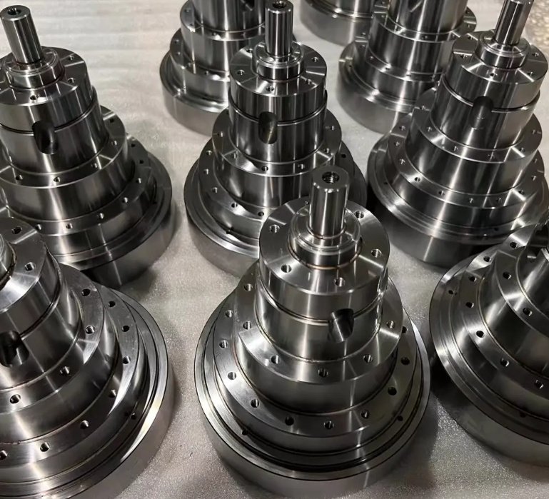
This precision metal manufacturing guide explains how high-accuracy metal parts are designed, machined, formed, inspected and improved for production. It is written for engineers, sourcing teams, product developers and quality managers who need predictable tolerances, repeatable performance and manufacturable designs.
In practical terms, precision metal manufacturing is not only about making a part “very accurate.” It is about achieving repeatable conformity to a specified print while controlling material behavior, machine capability, tooling wear, fixturing, thermal effects, surface finish, inspection uncertainty and production cost.
What Is Precision Metal Manufacturing?
Precision metal manufacturing is the controlled production of metal components with defined dimensional tolerances, geometric tolerances, material requirements and surface quality. It can include CNC machining, Swiss turning, sheet metal fabrication, laser cutting, metal stamping, wire EDM, casting, forging, grinding, welding, additive manufacturing and post-processing.
A precision part is usually defined by a combination of:
- Dimensional tolerances such as ±0.005 in, ±0.001 in, ±0.05 mm or ±0.01 mm
- Geometric Dimensioning and Tolerancing, commonly known as GD&T
- Surface roughness, such as Ra 3.2 μm, Ra 1.6 μm or Ra 0.4 μm
- Material grade and condition, such as 6061-T6 aluminum, 304 stainless steel or 17-4PH H900
- Heat treatment, plating, passivation, anodizing or coating requirements
- Inspection method, sampling plan and acceptance criteria
Standards often referenced in precision metal manufacturing include ISO 9001, AS9100, ISO 2768, ISO 286, ASME Y14.5 for GD&T, ASTM material specifications and industry-specific requirements for medical, aerospace, automotive, energy and electronics applications.
Core Precision Metal Manufacturing Processes
The best process depends on tolerance, geometry, volume, material, lead time and cost target. A prototype bracket, a titanium surgical component and a high-volume electrical contact may all be “precision metal parts,” but they require very different manufacturing strategies.
| Process | Typical Use | Common Tolerance Range | Key Advantage | Main Limitation |
|---|---|---|---|---|
| CNC milling | Prismatic parts, housings, brackets, fixtures, mold components | ±0.005 in to ±0.001 in; tighter with process control | High flexibility and good accuracy | Cost rises with deep pockets, tight tolerances and complex setups |
| CNC turning | Shafts, bushings, pins, threaded parts, round components | ±0.003 in to ±0.0005 in for selected features | Efficient for rotational geometry | Non-round features may require live tooling or secondary milling |
| Swiss machining | Small, slender, high-volume precision parts | ±0.0005 in to ±0.002 in depending on feature and material | Excellent concentricity and productivity for small parts | Less suitable for large or highly prismatic parts |
| Wire EDM | Hard metals, tool steel, fine slots, dies, intricate profiles | ±0.0002 in to ±0.001 in in controlled applications | No cutting force and excellent profile accuracy | Slower than machining and limited to conductive materials |
| Sheet metal fabrication | Enclosures, chassis, panels, brackets, covers | ±0.005 in to ±0.030 in depending on feature and bend sequence | Cost-effective for lightweight structural parts | Bend variation, grain direction and springback must be managed |
| Metal stamping | High-volume clips, contacts, washers, brackets and formed components | ±0.001 in to ±0.010 in depending on die and material | Low unit cost at scale | Tooling investment and design freeze are required |
| Precision casting | Complex shapes, impellers, housings, near-net components | Process dependent; machining often required on critical features | Complex geometry with reduced material waste | Shrinkage, porosity and dimensional variation need control |
| Metal additive manufacturing | Complex internal channels, lightweight structures, low-volume parts | Often requires finish machining for critical interfaces | High design freedom | Surface finish, anisotropy and qualification cost can be significant |
Tolerances, GD&T and Process Capability
Tolerance is one of the largest cost drivers in precision manufacturing. A feature held to ±0.01 mm may require a different machine, setup, toolpath, fixture, temperature control and inspection method than a feature held to ±0.10 mm. The key is not to make every dimension tight, but to define what is truly critical.
Manufacturing teams often evaluate process capability using Cp and Cpk. In many production environments, a Cpk of 1.33 is considered a common minimum for capable production, while 1.67 or higher may be requested for safety-critical or high-risk features. The exact requirement depends on the customer, industry and consequence of failure.
Common Precision Tolerance Guidance
- General machined features: ±0.13 mm or ±0.005 in may be economical for many CNC parts.
- Precision bores, bearing seats and dowel holes: ±0.025 mm or ±0.001 in may be realistic with proper tooling and inspection.
- Grinding or honing features: ±0.005 mm to ±0.01 mm can be achievable depending on geometry and material.
- Sheet metal bends: angular and flange tolerances are affected by material thickness, bend radius, grain direction and press brake setup.
- Cast or additive near-net surfaces: critical datums often require secondary machining.
Engineering note: why over-tolerancing increases cost
If a non-critical pocket depth is specified at ±0.01 mm instead of ±0.10 mm, the supplier may need extra finishing passes, tool wear monitoring, in-process probing and more frequent inspection. On a 500-piece order, that can add hours of machine time without improving product function. A better approach is to apply tight tolerances only to critical-to-function features such as bearing fits, sealing surfaces, datum interfaces, precision slots and alignment holes.
Material Selection for Precision Metal Parts
Material selection affects machinability, dimensional stability, corrosion resistance, strength, weight, conductivity, finish quality and total cost. Two materials with similar strength may behave very differently during cutting, forming, welding or heat treatment.
| Material | Typical Benefits | Manufacturing Considerations | Common Applications |
|---|---|---|---|
| Aluminum 6061-T6 | Lightweight, good machinability, good corrosion resistance | Can anodize well; thin walls may distort during machining | Housings, brackets, fixtures, electronics components |
| Aluminum 7075-T6 | High strength-to-weight ratio | More expensive than 6061; corrosion protection may be needed | Aerospace parts, high-load structures, robotics |
| Stainless steel 304 | Good corrosion resistance and formability | Work hardening can increase tool wear | Food equipment, medical hardware, enclosures |
| Stainless steel 316 | Improved corrosion resistance in chloride environments | Generally slower to machine than free-machining stainless grades | Marine, chemical, medical and fluid handling parts |
| 17-4PH stainless steel | High strength after precipitation hardening | Heat treatment affects final dimensions and should be planned | Aerospace, valves, shafts, precision mechanical parts |
| Low carbon steel | Cost-effective and weldable | May require plating, painting or coating for corrosion protection | Frames, brackets, structural components |
| Titanium Grade 5 | High strength, low density, excellent corrosion resistance | Low thermal conductivity makes machining slower and more tool-intensive | Medical implants, aerospace, high-performance components |
| Copper and brass | High conductivity and good corrosion resistance | Copper can be gummy; brass is often easier to machine | Electrical contacts, heat sinks, fittings, RF components |
Design for Manufacturing in Precision Metal Production
A well-designed part reduces scrap, machine time and inspection burden. Design decisions made before quoting often determine whether a precision metal component is stable in production or difficult to control.
DFM Rules That Commonly Reduce Cost
- Use standard hole sizes, thread sizes, cutter radii and sheet gauges when possible.
- Avoid unnecessarily deep, narrow pockets that require long-reach tools.
- Specify realistic inside corner radii for CNC milling instead of sharp internal corners.
- Use datums that match how the part will be fixtured and inspected.
- Keep wall thickness consistent where possible to reduce distortion and heat concentration.
- Design bend reliefs, adequate flange lengths and proper inside bend radii for sheet metal parts.
- Separate cosmetic surfaces from functional surfaces on the drawing.
- Clarify which dimensions are reference, inspection-critical or controlled by GD&T.
Effective Design for Manufacturing reviews should involve manufacturing engineering, quality engineering and purchasing before the drawing is released. This is especially important when parts require tight positional tolerance, flatness, perpendicularity, concentricity, sealing surface finish or post-machining heat treatment.
Engineering note: tolerance stack-up in assemblies
A common assembly issue occurs when each component meets its drawing but the final product does not align. This is a tolerance stack-up problem. For example, five plates each allowed ±0.10 mm positional variation can create up to 1.00 mm total worst-case misalignment across two directions if datum strategy is not controlled. Statistical stack-up may show lower expected variation, but safety-critical and precision alignment systems often need datum optimization, dowel location or selective assembly.
Machining Variables That Affect Accuracy
Precision metal manufacturing depends on process stability. Even with a capable CNC machine, uncontrolled inputs can create dimensional drift, poor finish, burrs, taper, chatter or out-of-round features.
Important Process Variables
- Tool geometry: rake angle, flute count, coating and edge preparation affect cutting forces and finish.
- Tool wear: a worn end mill can change part size, increase burrs and cause poor surface roughness.
- Workholding: clamping pressure can distort thin-wall parts before machining.
- Thermal growth: machine spindles, tools and workpieces expand with temperature changes.
- Cutting parameters: feed rate, spindle speed, depth of cut and coolant strategy influence accuracy.
- Toolpath strategy: roughing, rest machining, climb milling and finish passes affect final geometry.
- Material condition: residual stress in plate, bar or casting can release during material removal.
For high-precision CNC machining, many manufacturers use rough machining, stress relief, semi-finishing and final finishing to improve dimensional stability. In-process probing, tool length compensation and controlled shop temperature can further reduce variation.
Engineering note: thin-wall aluminum housing distortion
A thin-wall 6061-T6 aluminum electronics housing with 2.0 mm walls may measure within tolerance while clamped but bow after release. In one typical corrective approach, roughing leaves 0.3 mm stock, the part rests for stress relaxation, soft jaws support the finished profile, and final passes remove equal stock from both sides. This type of process change can reduce flatness variation from about 0.25 mm to less than 0.08 mm when fixturing and cutting parameters are properly controlled.
Surface Finish, Burr Control and Edge Quality
Surface finish affects sealing, friction, fatigue life, appearance, coating adhesion, cleanability and wear. A roughness requirement should be functional rather than cosmetic unless the appearance is a defined product requirement.
Common surface finish callouts include Ra values such as 3.2 μm for general machined surfaces, 1.6 μm for improved functional surfaces, and 0.8 μm or lower for sealing, sliding or precision bearing interfaces. Very fine finishes may require grinding, lapping, polishing, honing or special tooling.
Deburring and Edge Finishing Methods
- Manual deburring for low-volume or complex parts
- Vibratory tumbling for batch edge smoothing
- Brush deburring for machined edges and cross holes
- Thermal deburring for internal burrs in selected materials
- Electropolishing for stainless steel micro-burr reduction and surface improvement
- Chamfering or edge break machining for controlled edge geometry
Drawings should distinguish between “break sharp edges,” maximum burr height, controlled chamfer size and safety-critical edge radius. Vague edge requirements can lead to inconsistent parts, especially in medical devices, fluid systems and moving assemblies where surface integrity affects performance.
Quality Control and Inspection Methods
Precision manufacturing is incomplete without measurable verification. The inspection plan should match the risk of the part, the tolerance level and the production volume.
| Inspection Method | Best For | Limitations |
|---|---|---|
| Calipers and micrometers | Basic linear dimensions, diameters, thickness checks | Operator technique and access can affect repeatability |
| Height gauge and surface plate | Heights, flatness checks, layout inspection | Requires stable setup and proper datum contact |
| CMM inspection | GD&T, complex geometry, positional tolerance, datums | Programming strategy and fixture stability are critical |
| Optical comparator | Profiles, small features, stamped parts, radii | Less suitable for hidden 3D geometry |
| Surface roughness tester | Ra, Rz and texture measurement | Cutoff length and measurement direction must be defined |
| Go/no-go gauges | High-volume functional checks | Less diagnostic than variable measurement data |
| Non-destructive testing | Cracks, porosity, weld defects and internal flaws | Method selection depends on material and defect type |
For new or revised parts, a first article inspection verifies that the manufacturing process can produce the drawing requirements before full production. For ongoing production, control plans may include in-process inspection, final inspection, SPC charts, gauge R&R studies and lot traceability.
Real Engineering Problems and Practical Improvements
The following examples show how manufacturing problems are often solved through process control rather than simply requesting “better machining.”
Problem 1: Stainless Steel Burrs in Cross Holes
A 316 stainless valve component developed internal burrs where a 2.5 mm cross hole intersected a 6 mm bore. The burrs caused seal damage during assembly. The original process used a standard drill and manual external deburring only.
- Root cause: ductile material, drill exit burrs and no internal burr removal method.
- Improvement: peck drilling optimization, sharper coated drill, internal brush deburring and 100% borescope sampling during validation.
- Result: measured burr height reduced from approximately 0.12 mm to less than 0.03 mm, and assembly seal damage was eliminated during the validation build.
Problem 2: Positional Drift in Multi-Setup CNC Parts
A machined aluminum sensor bracket required four precision mounting holes at true position 0.05 mm relative to a machined datum face. Parts were drifting out of tolerance after the second setup.
- Root cause: inconsistent manual locating against a saw-cut edge and clamp-induced movement.
- Improvement: machine datum features in the first setup, use hardened locating pins, reduce clamping force and inspect with a CMM program aligned to functional datums.
- Result: positional variation improved from a 0.09 mm spread to a 0.028 mm spread across a 30-piece capability run.
Problem 3: Sheet Metal Springback Variation
A 1.5 mm stainless steel bracket showed angle variation after bending, causing assembly interference. The drawing specified a tight flange location but did not define grain direction or bend sequence.
- Root cause: variable material springback and inconsistent bend order.
- Improvement: define grain direction, use consistent tooling, adjust bend allowance, add inspection after first bend and revise the datum scheme.
- Result: flange location variation decreased from ±0.45 mm to ±0.15 mm in production trials.
Cost Drivers in Precision Metal Manufacturing
Precision metal parts are priced by more than material weight. Cost is driven by engineering requirements, production risk and the amount of controlled processing required to make conforming parts.
Major Cost Factors
- Material grade, size, certification and availability
- Number of setups and part orientations
- Machine time, cycle time and required spindle speed or power
- Tooling, fixtures, gauges and custom workholding
- Tolerance tightness and inspection frequency
- Surface finish and cosmetic requirements
- Heat treatment, anodizing, plating, passivation, painting or coating
- Scrap risk due to expensive material or late-stage finishing
- Documentation such as material certificates, inspection reports and traceability
A practical quoting approach is to separate standard features from critical features. If only three dimensions on a part require high precision, the drawing should make that clear. This allows the manufacturer to focus machine capability, inspection time and process controls where they create measurable risk reduction.
How to Prepare a Precision Metal Manufacturing Drawing
A complete technical package reduces supplier interpretation and improves quote accuracy. When requesting precision metal manufacturing, include both the 3D model and a controlled 2D drawing.
Recommended Drawing and RFQ Checklist
- Provide CAD files in STEP, Parasolid or native format, plus a PDF drawing.
- Define material grade, condition, specification and any required certification.
- Identify critical dimensions and functional interfaces.
- Use GD&T where fit, alignment or datum control matters.
- Specify surface finish only where function requires it.
- Define edge break, burr limits and cosmetic expectations.
- List heat treatment, coating, plating, anodizing, passivation or cleaning requirements.
- State inspection requirements, reporting needs and sampling level.
- Clarify target quantity, annual volume and expected production schedule.
- Communicate assembly function, mating components and failure risks when appropriate.
Precision Metal Manufacturing Guide Summary
Successful precision metal manufacturing depends on matching the part design to the right process, material, tolerance strategy, tooling plan and inspection method. The most reliable outcomes come from clear drawings, realistic tolerances, stable fixturing, controlled machining parameters, suitable finishing processes and data-driven quality control.
For engineers and buyers, the most important takeaway is simple: define function first, then assign precision where it matters. This reduces cost, improves lead time and increases the probability that every production lot meets the intended performance requirements.