
Copper Machining Services
- Fast prototype & low MOQ support
- Tight tolerance up to +0.002mm
- Surface finishing available
- Engineering review before production
Carbon Steel CNC Machining Capabilities
Precision Milling
- Multi-axis CNC milling for complex geometries.
- Tight tolerances as tight as ±0.002mm and fine surface finishes.
- Suitable for prototypes and mass production.
CNC Turning
- High-speed turning for shafts, rods, and cylindrical parts.
- Thread cutting, grooving, and facing operations.
- Supports both small and large batch production.
Drilling, Tapping & Boring
- CNC drilling for holes of all sizes and depths.
- Threading and tapping for assemblies.
- High repeatability for precision alignment.
Multi-Axis Machining
- 4-axis and 5-axis machining for intricate parts.
- Reduced setups and improved accuracy.
- Ideal for aerospace, automotive, and medical components.
Secondary Operations
- Deburring, grinding, tapping, honing, keyways, broaching support.
- Specialized processes for hard-to-machine metals.
- Used when critical surfaces, fit, or assembly requirements exceed standard machining
CNC Prototyping
- Rapid CNC prototyping to test designs quickly.
- Small batch to full-scale production runs.
- Flexible workflow to meet tight deadlines.
Real Engineering Problems in Copper Machining
Heavy burrs on slots and holes
Likely Cause: Dull tool, low chip load, unsupported exit edge
Corrective Action: Use sharper tools, adjust feed, add backup support and define edge break
Typical Result: Reduced manual deburring time and more consistent assembly fit
Smeared surface on C110 copper
Likely Cause: Rubbing instead of cutting
Corrective Action: Increase effective chip load, use polished flutes and positive rake cutters
Typical Result: Cleaner surface finish and lower risk of embedded debris
Thread pullout in soft copper
Likely Cause: Insufficient engagement or high assembly torque
Corrective Action: Increase thread depth, use inserts, or change alloy where appropriate
Typical Result: Improved torque resistance and service durability
Part warping after pocketing
Likely Cause: Unbalanced material removal
Corrective Action: Rough both sides, normalize material removal and finish from stable datums
Typical Result: Improved flatness and repeatable inspection results
Contact resistance variation
Likely Cause: Tool marks, oxidation, contamination or inconsistent plating
Corrective Action: Control surface finish, cleaning, storage and finishing specifications
Typical Result: More predictable electrical performance
Common Copper Alloys for Machined Parts
Selecting the right copper alloy is often more important than selecting the machining process. Pure copper offers excellent conductivity, while alloyed coppers improve machinability, strength, wear resistance or spring properties.
| Copper Grade | Also Known As | Key Properties | Common Machined Applications |
|---|---|---|---|
| C101 | Oxygen-Free Electronic Copper, OFE Copper | Very high electrical and thermal conductivity, low oxygen content | Vacuum components, RF parts, semiconductor fixtures, high-purity conductive parts |
| C102 | Oxygen-Free Copper, OF Copper | High conductivity, good formability, excellent corrosion resistance | Electrical conductors, thermal parts, vacuum-compatible components |
| C110 | Electrolytic Tough Pitch Copper, ETP Copper | High conductivity, widely available, economical for many electrical parts | Bus bars, terminals, heat spreaders, grounding components, connectors |
| C145 | Tellurium Copper, TeCu | Improved machinability with good electrical and thermal conductivity | Switchgear parts, electrical contacts, precision turned copper components |
| C172 | Beryllium Copper, BeCu | High strength, fatigue resistance, wear resistance and spring performance | Springs, contact fingers, aerospace connectors, high-cycle electrical contacts |
| C18150 | Chromium Zirconium Copper | Good conductivity, high softening resistance, improved high-temperature strength | Resistance welding electrodes, mold components, heat-resistant conductive tooling |
Tolerances, Surface Finish and Inspection Expectations
| Requirement | Typical Achievable Range | Notes |
|---|---|---|
| General CNC milled features | ±0.05 mm to ±0.10 mm | Suitable for many copper brackets, bus bars, housings and plates |
| Precision milled or turned features | ±0.01 mm to ±0.025 mm | Requires stable geometry, controlled setup and appropriate inspection |
| Flatness on thin copper plates | Geometry-dependent | Often controlled by material thickness, clamping method and stress relief |
| Surface roughness | Ra 0.8 to 3.2 µm common | Finer finishes may require special tooling, polishing or secondary finishing |
| Threaded holes | Class depends on standard | Thread burrs and conductivity at contact areas should be specified when relevant |
Engineering note: why copper flatness can change after machining
Copper parts can appear flat while clamped but relax after removal from the fixture. This is common in thin plates, large heat spreaders and asymmetric pockets. Causes include residual stress in stock, uneven material removal, localized tool pressure and excessive clamping force. Process improvements include stress-balanced roughing, using thicker starting stock, finish machining both sides, supporting the full part footprint and specifying flatness only on functional datum surfaces when possible.
CNC Milling Copper: Practical Process Notes
CNC milling copper requires a balance between rigidity and gentle clamping. Excessive workholding force can deform thin copper plates, while insufficient support can cause vibration, chatter, tapered walls and uneven surface finish. Vacuum fixtures, soft jaws, sacrificial support plates and distributed clamping are commonly used for thin copper components.
- Use sharp carbide tools with polished flutes to reduce built-up edge.
- Apply positive rake cutting geometry to encourage shearing instead of smearing.
- Use controlled chip loads; rubbing creates heat, burrs and poor finish.
- Provide strong chip evacuation for deep slots, pockets and micro channels.
- Plan finishing passes after roughing stress has been released.
- Use coolant or lubricant based on cleanliness, conductivity and post-processing requirements.
Thin copper heat spreaders, for example, may meet dimensional tolerance at the machine but change flatness after unclamping if the fixture strategy is poor. A process that includes stress-balanced roughing, intermediate inspection and finish machining on supported datums can significantly improve final flatness.
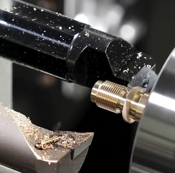
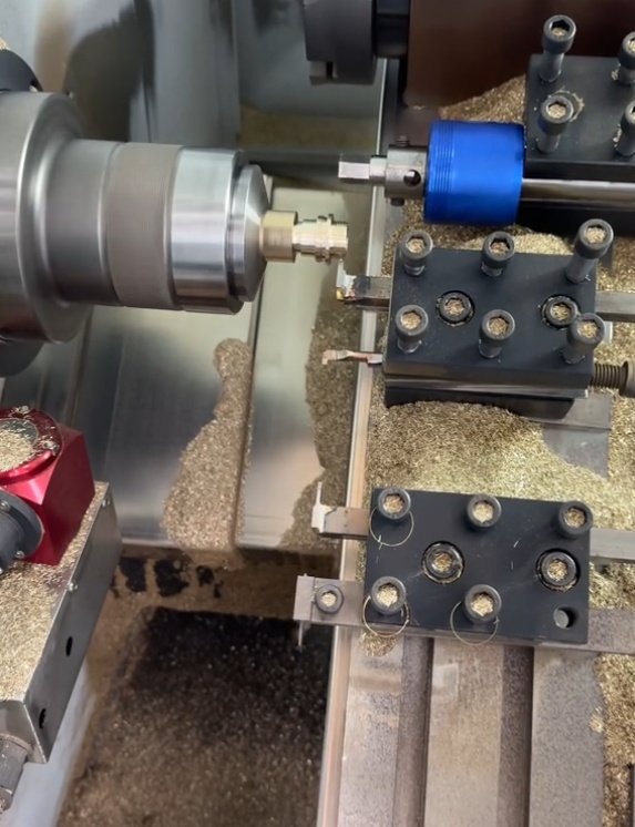
CNC Turning Copper: Contacts, Pins and Conductive Components
CNC turning is widely used for copper electrical pins, terminals, bushings, contacts, threaded studs, sleeves and electrode bodies. In turning operations, long continuous chips are a common problem, especially in pure copper grades. Chipbreaker inserts designed for steel may not perform as expected because copper flows differently at the cutting edge.
Effective CNC turning of copper typically uses sharp inserts, optimized feed rates, adequate tool nose radius, stable part support and toolpath planning that avoids work hardening or smearing on fine features. For small turned copper contacts, consistent burr control at shoulders, grooves and threads is often more critical than the nominal diameter tolerance.
| Turned Feature | Common Issue | Manufacturing Approach |
|---|---|---|
| Small pins | Deflection and diameter variation | Use guide bushings, optimized stick-out and support tooling |
| Fine threads | Thread crest burrs and tearing | Use sharp threading tools, controlled spring passes and post-thread deburring |
| Grooves | Chip packing and sidewall smearing | Use pecking, coolant targeting and proper groove tool geometry |
| Electrical contact faces | Tool marks affecting contact resistance | Use finishing cuts, lapping if required and controlled surface roughness |
Design Guidelines for Machined Copper Parts
- Use generous internal radii where possible; sharp internal corners require smaller tools and longer cycle times.
- Avoid very thin unsupported walls unless they are essential to function.
- Specify edge breaks for conductive parts that must be handled or assembled without cutting insulation or damaging mating parts.
- Identify contact areas where scratches, burrs, oxidation or coatings are not acceptable.
- Separate cosmetic requirements from functional requirements on the drawing.
- Use C145 or other free-machining copper alloys when conductivity requirements allow.
- For threaded copper parts, verify torque loads and consider inserts if repeated assembly is expected.
- For heat transfer parts, define flatness, surface roughness and interface material requirements together.
Design note: copper heat sinks and cooling plates
Copper has higher thermal conductivity than aluminum, but it is denser, more expensive and more challenging to machine. For liquid cooling plates, manufacturability depends on channel width, channel depth, cover method, sealing surface finish and pressure requirements. Deep narrow channels increase tool deflection and chip evacuation difficulty. If thermal simulation allows, slightly wider channels and larger corner radii can reduce machining risk while preserving cooling performance.
Finishing Options for Copper Components
Copper finishes are selected based on conductivity, corrosion resistance, solderability, wear resistance, appearance and storage conditions. Because copper oxidizes naturally, finish planning should be considered early in the design process, especially for electrical contact parts.
| Finish | Purpose | Considerations |
|---|---|---|
| As-machined | Functional surfaces, prototypes, internal components | May show tool marks and will oxidize over time |
| Mechanical polishing | Improved appearance or smoother contact surfaces | Can round edges and alter flatness if uncontrolled |
| Nickel plating | Corrosion resistance, diffusion barrier, wear improvement | May reduce exposed copper conductivity at contact areas |
| Tin plating | Solderability and electrical contact protection | Common for terminals, bus bars and connectors |
| Silver plating | High-conductivity electrical contact surface | Good contact performance but may tarnish depending on environment |
| Gold plating | Low contact resistance and oxidation resistance | Often used for high-reliability contacts and RF components |
| Passivation or anti-tarnish treatment | Short-term oxidation control | Must be compatible with electrical and soldering requirements |
For electrical parts, the phrase conductive surface finish should be defined carefully. A finish may protect the copper from oxidation but change contact resistance, solderability or wear behavior. Drawings should state which surfaces require plating and which must remain bare copper.
Quality Control and Measurement for Copper Machined Parts
- First article inspection for critical dimensions and datum structure.
- In-process checks for features affected by tool wear or burr formation.
- Surface roughness verification for sealing, thermal interface or contact areas.
- Flatness and parallelism inspection using controlled support conditions.
- Material certification for copper grade, temper and relevant standards.
- Plating thickness and adhesion checks when secondary finishing is specified.
Inspection note: measuring soft copper parts
Soft copper can be marked by hard probes, clamps or gauge pressure. For delicate surfaces, low-force measurement, optical inspection or protected datums may be preferred. When checking flatness, the support method should match the drawing requirement; measuring a thin copper plate while it is forced flat can hide real assembly issues.
Industries and Applications
Custom machined copper parts are used wherever conductivity, heat transfer, corrosion resistance or durable electrical contact is needed. Typical industries include electronics, semiconductor equipment, power generation, electric vehicles, battery systems, aerospace, defense, medical devices, telecommunications, industrial automation and energy storage.
| Industry | Typical Copper Machined Parts |
|---|---|
| Electronics and Power Distribution | Bus bars, terminals, grounding blocks, switchgear contacts, conductive plates |
| Thermal Management | Heat sinks, heat spreaders, cold plates, vapor chamber components, thermal blocks |
| Semiconductor Equipment | Vacuum-compatible copper parts, RF components, fixtures, high-purity conductive parts |
| Electric Vehicles and Batteries | Battery tabs, current collectors, power connectors, inverter components |
| Aerospace and Defense | Connectors, RF housings, BeCu spring contacts, precision conductive hardware |
| Industrial Manufacturing | Resistance welding electrodes, wear-resistant conductive tooling, sensor components |
Material Safety and Beryllium Copper Considerations
Material note: when to choose beryllium copper
Beryllium copper may be appropriate when a part must behave like a spring, withstand repeated cycles, resist wear and maintain electrical conductivity. If the part is mainly a conductor and does not need high strength or fatigue resistance, C110, C145 or C18150 may be more practical and economical.
How to Prepare Drawings for Copper Machining
A complete drawing or 3D model helps prevent ambiguity and reduces manufacturing risk. For copper machining projects, engineering documentation should include material grade, temper, critical dimensions, datums, surface finish requirements, plating requirements, inspection criteria and packaging expectations.
- Specify the exact copper alloy, such as C101, C110, C145, C172 or C18150.
- Define whether conductivity, strength, solderability or corrosion resistance is most important.
- Mark critical electrical contact surfaces and thermal interface surfaces.
- State tolerance classes only where they are functionally necessary.
- Include edge break requirements, especially near holes, slots and contact edges.
- Clarify plating masking areas and allowable plating buildup on tight features.
- Indicate inspection method if flatness, surface roughness or contact resistance is critical.
- Identify packaging needs to prevent scratches, oxidation or contamination.
The best results come from matching design intent to manufacturable specifications. Copper parts that look simple on a drawing can become difficult if they combine thin walls, tight flatness, small threaded holes, cosmetic finish requirements and high conductivity surfaces without a clear priority.
Why Copper Machining Requires Specialized CNC Experience
Copper machining is a specialized manufacturing discipline because the material rewards precision but exposes weak process planning. A capable CNC process controls tool geometry, feed strategy, workholding, chip evacuation, deburring, inspection and finishing as one system.
For high-performance copper components, the goal is not only to machine the correct shape. The goal is to deliver parts with reliable conductivity, consistent assembly behavior, controlled surface condition and repeatable dimensional quality. That requires understanding the difference between machining pure copper, free-machining copper, chromium zirconium copper and beryllium copper components.
Whether the requirement is a prototype copper heat sink, a production bus bar, a precision electrical contact, a custom copper electrode or a complex CNC milled copper housing, material-aware machining decisions directly affect cost, yield and performance.