
Inconel Machining Services
Inconel machining services support the production of high-performance nickel alloy components used in aerospace, energy, marine, chemical processing, defense, medical, and oil and gas applications. Inconel alloys are selected for excellent corrosion resistance, oxidation resistance, creep strength, fatigue resistance, and mechanical stability at elevated temperatures. However, these same properties make Inconel difficult to machine without the right CNC process, tooling, coolant strategy, and inspection plan.
- Fast prototype & low MOQ support
- Tight tolerance up to +0.002mm
- Surface finishing available
- Engineering review before production
Inconel CNC Machining Capabilities
Common Inconel CNC machining processes include 3-axis milling, 4-axis milling, 5-axis machining, CNC turning, mill-turn machining, boring, reaming, grooving, parting, drilling, thread milling, tapping, broaching alternatives, wire EDM, sinker EDM, grinding, and final deburring. Inconel components often combine complex geometry with demanding mechanical requirements. Machining capability must address not only part shape but also repeatability, surface integrity, burr control, and inspection traceability. Typical project requirements may include tolerances from ±0.005 in to ±0.001 in depending on geometry, feature size, datum structure, wall thickness, and inspection method. For metric drawings, common CNC-machined Inconel tolerances may range from ±0.13 mm to ±0.005 mm, with tighter tolerances evaluated by feature and production volume.
Precision Milling
- Multi-axis CNC milling for complex geometries.
- Tight tolerances as tight as ±0.002mm and fine surface finishes.
- Suitable for prototypes and mass production.
CNC Turning
- High-speed turning for shafts, rods, and cylindrical parts.
- Thread cutting, grooving, and facing operations.
- Supports both small and large batch production.
Drilling, Tapping & Boring
- CNC drilling for holes of all sizes and depths.
- Threading and tapping for assemblies.
- High repeatability for precision alignment.
Multi-Axis Machining
- 4-axis and 5-axis machining for intricate parts.
- Reduced setups and improved accuracy.
- Ideal for aerospace, automotive, and medical components.
Secondary Operations
- Deburring, grinding, tapping, honing, keyways, broaching support.
- Specialized processes for hard-to-machine metals.
- Used when critical surfaces, fit, or assembly requirements exceed standard machining
CNC Prototyping
- Rapid CNC prototyping to test designs quickly.
- Small batch to full-scale production runs.
- Flexible workflow to meet tight deadlines.
Prototype and Production Inconel Machining
Prototype Inconel machining focuses on proving geometry, material behavior, assembly fit, and inspection methods. Production machining focuses on repeatability, cycle time, tool life management, process control, and documented quality. A successful production process usually includes stable fixturing, defined tool change intervals, in-process probing or inspection, controlled finishing allowance, and repeatable deburring.
For small batches, CNC programming flexibility and setup planning may be more important than maximum material removal rate. For production quantities, toolpath optimization, coolant delivery, insert indexing strategy, and statistical process control can reduce cost per part while protecting critical dimensions.
Common Inconel Grades We Machine
Different Inconel grades behave differently during machining. Some are solid-solution strengthened, while others are precipitation hardened. Grade selection affects tool life, chip formation, heat generation, cutting forces, and post-machining stability.
| Inconel Grade | Typical Applications | Machining Considerations |
|---|---|---|
| Inconel 625 | Marine hardware, chemical equipment, valve bodies, manifolds, subsea components | Excellent corrosion resistance; gummy chip behavior; requires sharp carbide and strong coolant flow |
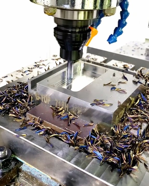
| Inconel 718 | Aerospace brackets, turbine parts, fasteners, oilfield components, high-strength shafts | Inconel 718 is precipitation hardened and maintains strength at high temperature; tool wear and notch wear must be controlled |
| Inconel 600 | Heat-treat fixtures, furnace components, chemical processing parts | Good oxidation resistance; tends to work harden if feeds are too light |
| Inconel 601 | Thermal processing equipment, combustion systems, radiant tubes | High oxidation resistance; heat control is critical during long cuts |
| Inconel X-750 | Springs, fasteners, turbine components, high-temperature structural parts | High strength after heat treatment; requires stable clamping and careful toolpath planning |
| Inconel 725 | Oil and gas components, sour service equipment, marine fasteners | High strength and corrosion resistance; drilling and threading need controlled peck cycles and coolant pressure |
Machining Strategy: Tooling, Speeds, Feeds and Coolant
Cutting Tools
Carbide tooling is commonly used for milling, turning, drilling, and threading Inconel. Tool grades with heat-resistant coatings such as AlTiN, TiAlN, or advanced PVD coatings are frequently selected. Edge preparation must be controlled: too sharp may chip, while too honed may increase cutting pressure. Ceramic tools can be used in specific high-speed rough turning applications, but they are not suitable for every setup or interrupted cut.Coolant and Chip Control
Flood coolant or high-pressure coolant is used to remove heat, improve chip evacuation, and reduce built-up edge. For turning and drilling, high-pressure coolant can significantly improve tool life when directed at the cutting edge. In deep holes, poor chip evacuation may cause drill failure, oversize holes, poor surface finish, or tool breakage.Typical Parameter Ranges
The following ranges are general starting points for discussion, not universal settings. Final parameters should be validated by part geometry, tool supplier data, machine condition, and inspection results.| Operation | Common Tooling | Typical Strategy | Key Risk |
|---|---|---|---|
| Rough milling | Coated carbide end mills, indexable cutters | Moderate depth of cut, stable engagement, constant chip load | Chatter, notch wear, heat concentration |
| Finish milling | Sharp coated carbide, ball end mills, corner radius end mills | Consistent finishing allowance and minimal tool deflection | Dimensional drift and surface tearing |
| Turning | Coated carbide inserts, positive geometry where applicable | Rigid clamping, controlled depth of cut, coolant aimed at edge | Notch wear and work-hardened skin |
| Drilling | Carbide drills, coolant-through drills | Short, stable tools with chip evacuation strategy | Chip packing, heat, hole oversize |
| Threading | Thread mills, carbide taps, single-point threading tools | Controlled engagement and verified thread gaging | Tap breakage and poor thread finish |
Practical result: improving tool life in an Inconel 718 turning operation
In one representative turning setup for aged Inconel 718, replacing a general-purpose carbide insert with a heat-resistant coated insert, reducing radial engagement at the notch line, and directing high-pressure coolant to the cutting zone reduced insert changes from approximately every 8 parts to approximately every 15 parts. The measured benefit was a 40% to 50% reduction in tool-related downtime for that operation. Actual results vary by hardness, geometry, machine rigidity, and coolant pressure.
Why Inconel Is Difficult to Machine
- Work hardening: If feed per tooth or feed per revolution is too low, the tool can rub the surface and create a hardened layer that damages the next cutting edge.
- Low thermal conductivity: Heat remains near the cutting zone instead of flowing into the chip or workpiece evenly, increasing crater wear and edge breakdown.
- High cutting forces: Rigid machines, short tool overhang, strong workholding, and stable toolpaths are needed to reduce chatter.
- Notch wear: Inconel often causes concentrated wear at the depth-of-cut line, especially in turning and shoulder milling.
- Built-up edge: Poor chip evacuation or incorrect tool geometry can lead to material welding on the cutting edge.
- Residual stress sensitivity: Aggressive machining, poor fixturing, or uneven stock removal may cause movement in thin-wall or heat-treated parts.
Engineering note: why rubbing is more damaging in Inconel than in free-machining alloys
In free-machining steels or aluminum, a short period of rubbing may reduce finish quality but may not immediately destroy the cutting edge. In Inconel, rubbing can rapidly harden the surface and increase local temperature. Once the tool re-enters that hardened layer, cutting force rises and tool wear accelerates. This is why many Inconel programs avoid extremely light finishing passes unless the tool is sharp, the setup is rigid, and the feed is sufficient to maintain a real chip.
Design for Manufacturability in Inconel CNC Parts
Design decisions have a large impact on cost, lead time, tool life, and risk. Inconel parts become more expensive when the drawing includes deep narrow pockets, very small internal radii, long thin walls, deep threaded holes, sharp internal corners, excessive surface finish requirements, or tight tolerances applied to non-critical features.
- Use practical internal radii so end mills do not need to cut with excessive tool engagement.
- Avoid unnecessarily deep pockets with small corner radii unless functionally required.
- Specify tight tolerances only on functional interfaces, sealing faces, bearing fits, datum features, and assembly-critical geometry.
- Allow reasonable wall thickness to reduce vibration, distortion, and heat-related movement.
- Consider thread milling for expensive parts, large internal threads, difficult blind holes, and features where broken taps create high scrap risk.
- Define surface roughness requirements clearly, such as Ra 32 µin, Ra 16 µin, Ra 0.8 µm, or application-specific sealing requirements.
- Provide material condition, heat treatment, hardness range, grain direction if relevant, and any required material certifications.
When drawings require thin walls below 1.0 mm, deep slots with length-to-width ratios above 8:1, or true position tolerances below 0.05 mm, the machining plan may need custom fixturing, stress-relief sequencing, semi-finish operations, and in-process inspection.
Quality Control and Inspection for Inconel Machined Components
- CMM inspection for datum relationships, true position, profile, flatness, perpendicularity, and complex geometry
- Optical inspection for small features, edge conditions, engraved markings, and fine profiles
- Thread plug gages, ring gages, pitch micrometers, and thread profile verification
- Surface roughness measurement for sealing surfaces, sliding interfaces, and fatigue-sensitive areas
- Hardness verification when required by specification or heat treatment condition
- Material test reports for alloy traceability, including chemistry and mechanical properties where specified
- First article inspection reports for aerospace, defense, energy, and regulated manufacturing requirements
Inspection example: controlling bore size after heat generated by machining
A bored Inconel 625 sleeve with a tight internal diameter tolerance may measure within specification immediately after machining but shift after thermal equalization if inspected too soon. A stable process may require staged boring, rest time, temperature-controlled inspection, and final sizing with a sharp tool. This is especially important for thick-wall parts, high material removal rates, and precision fits below ±0.025 mm.
Industries and Applications
| Industry | Common Machined Parts | Performance Requirement |
|---|---|---|
| Aerospace | Brackets, housings, turbine-related hardware, fasteners, bushings | High strength, heat resistance, fatigue resistance, traceability |
| Oil and Gas | Valve parts, couplings, downhole tools, seal retainers, connectors | Sour service resistance, pressure capability, corrosion resistance |
| Marine | Fasteners, shafts, pump components, seawater-exposed hardware | Chloride corrosion resistance and long service life |
| Chemical Processing | Nozzles, fittings, reactor hardware, heat exchanger components | Resistance to acids, oxidation, and aggressive chemicals |
| Power Generation | Combustion hardware, thermal shields, high-temperature fixtures | Oxidation resistance, creep strength, dimensional stability |
Common Engineering Problems Solved in Inconel Machining
- Reducing distortion in thin-wall Inconel 625 parts by balancing roughing passes on opposite sides before final finishing
- Improving hole quality in Inconel 718 by replacing conventional peck drilling with coolant-through carbide drilling and controlled chip evacuation
- Preventing broken taps by using thread milling for blind holes, large internal threads, and expensive components
- Controlling sealing surface finish by separating roughing, semi-finishing, and final finishing tools
- Reducing chatter in long-reach milling by changing tool length, holder style, radial engagement, and toolpath strategy
- Maintaining true position by machining datums early, using repeatable workholding, and verifying features with in-process inspection
Data point: thread milling versus tapping in high-value Inconel parts
For blind internal threads in Inconel 718 and 625, thread milling can reduce scrap risk because the tool is smaller than the final thread diameter and can usually be removed if wear or breakage occurs. Although cycle time may be longer than tapping, the method can be more economical when the part has high material value, long machining time before threading, or a strict no-rework requirement.
How to Specify an Inconel Machined Part
Clear specifications help reduce quoting uncertainty and improve manufacturing outcomes. A complete technical package should include the 3D model, 2D drawing, alloy grade, material condition, quantity, revision level, critical features, tolerances, surface finish, inspection requirements, and any industry standards that apply.
- Alloy grade: Inconel 625, 718, 600, 601, X-750, 725, or another nickel alloy
- Material condition: annealed, solution treated, aged, precipitation hardened, or customer-supplied stock
- Dimensional tolerances and GD&T callouts, including datums and critical-to-function dimensions
- Surface finish requirements for sealing, fatigue, cosmetic, or sliding surfaces
- Thread standards such as UNC, UNF, UNEF, NPT, BSPP, metric coarse, metric fine, or custom thread forms
- Inspection documentation such as first article inspection, material certificates, CMM reports, or process records
- Post-machining requirements such as cleaning, marking, edge break, heat treatment, coating, or packaging