
Cast Iron Machining Services
- Fast prototype & low MOQ support
- Tight tolerance up to +0.002mm
- Surface finishing available
- Engineering review before production
Cast Iron CNC Machining Capabilities
Precision Milling
- Multi-axis CNC milling for complex geometries.
- Tight tolerances as tight as ±0.002mm and fine surface finishes.
- Suitable for prototypes and mass production.
CNC Turning
- High-speed turning for shafts, rods, and cylindrical parts.
- Thread cutting, grooving, and facing operations.
- Supports both small and large batch production.
Drilling, Tapping & Boring
- CNC drilling for holes of all sizes and depths.
- Threading and tapping for assemblies.
- High repeatability for precision alignment.
Multi-Axis Machining
- 4-axis and 5-axis machining for intricate parts.
- Reduced setups and improved accuracy.
- Ideal for aerospace, automotive, and medical components.
Secondary Operations
- Deburring, grinding, tapping, honing, keyways, broaching support.
- Specialized processes for hard-to-machine metals.
- Used when critical surfaces, fit, or assembly requirements exceed standard machining
CNC Prototyping
- Rapid CNC prototyping to test designs quickly.
- Small batch to full-scale production runs.
- Flexible workflow to meet tight deadlines.
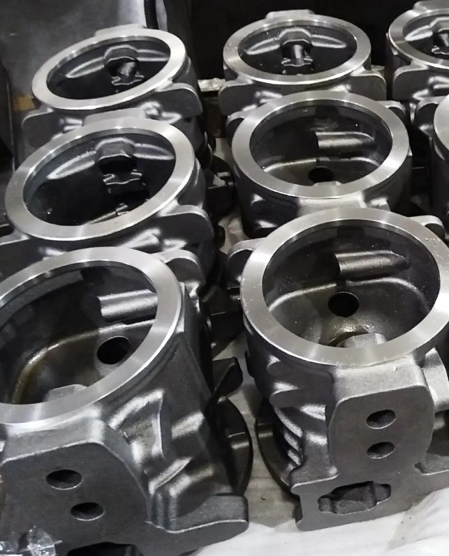
Industries and Part Types
Where cast iron remains the right material choice, suppliers need high-volume repeatability as much as one-off precision. The best machining process is the one that keeps size, position, and finish stable across multiple heats and foundry lots, not just on the first sample.
- Automotive and commercial vehicle: brake components, bearing carriers, engine-related structures, flywheel housings
- Pumps and fluid handling: pump casings, impeller housings, valve bodies, manifolds
- Power transmission: gearbox housings, covers, bearing supports, pulleys
- Industrial equipment: machine bases, slides, frames, counterweights, damped structures
- Energy and compressors: compressor bodies, support castings, pressure-related components after validation
- Agriculture and off-highway: hubs, knuckles, mounts, brackets, and structural cast parts
Why Cast Iron Requires a Specialized CNC Process
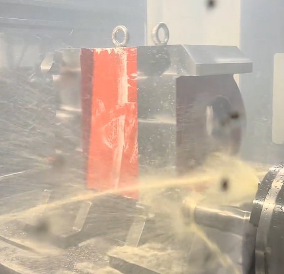
Cast iron behaves differently from steel, aluminum, or wrought stainless because of its graphite-rich microstructure. That graphite can improve chip breakage and damping, but it also creates abrasive dust, affects edge wear, and changes how the material responds to drilling, tapping, or interrupted milling. Shops that machine cast iron every day usually design the process around these realities rather than forcing a generic metal-cutting approach onto the part.
Gray iron is often considered one of the easier ferrous materials to machine because chips break well and vibration damping is good. Ductile iron is tougher, generates higher cutting forces, and can produce stringier chips. Compacted graphite iron sits between gray and ductile iron in some respects, but often behaves like a more demanding material during milling and boring because tool life drops faster and rigidity matters more.
- Raw cast skin can be harder than the core material and may contain chilled areas
- Graphite dust can contaminate machines if extraction and cleaning are not managed
- Porosity may not appear until a sealing face or port is opened by machining
- Residual stress and uneven wall thickness can move features after roughing
- Datum selection is more sensitive because the raw casting is rarely uniform
These factors are why cast iron machining is usually evaluated by process capability, not only by spindle size or advertised tolerance.
Cast Iron Grades Commonly Machined
| Cast iron grade | Common standards | General machinability | Typical parts | Machining notes |
|---|---|---|---|---|
| Gray iron | ASTM A48 Class 30, 40 | Very good | Machine bases, pump housings, pulleys, gearbox bodies | Good chip breakage and damping; often suited to dry milling and turning |
| Ductile iron | ASTM A536 65-45-12, 80-55-06 | Good to moderate | Bearing carriers, hubs, brackets, valve bodies, suspension parts | Higher strength and toughness; more cutting force and tougher chip control |
| Compacted graphite iron (CGI) | ISO 16112 / GJV grades | Moderate to difficult | Engine blocks, exhaust-side components, diesel structures | Tool life is more sensitive to rigidity, insert grade, and engagement strategy |
| Austempered ductile iron (ADI) | ASTM A897 | Difficult | Wear parts, gears, high-strength structural castings | Higher hardness; often requires feasibility review and premium tooling |
CNC Operations, Tolerances, and Surface Finishes
On many industrial castings, precision boring and finish milling define the functional success of the part. A pump body may need a flat gasket face, a valve manifold may need accurate port location, and a bearing housing may depend on bore size, roundness, and alignment more than on any outside dimension.
| Feature type | Typical production capability | Common finish range | Process notes |
|---|---|---|---|
| Milled mounting faces | ±0.05 mm typical, tighter on stable features | Ra 1.6-3.2 µm | Flatness depends on wall stiffness, stock balance, and fixture support |
| Turned outside diameters and registers | ±0.02 mm to ±0.05 mm | Ra 1.6-3.2 µm | Interrupted cuts and cast skin influence insert life |
| Bored bearing seats and critical IDs | ±0.01 mm or better where geometry permits | Ra 0.8-1.6 µm | Bore location and cylindricity depend on clamp strategy and tool overhang |
| Drilled and tapped holes | Position typically ±0.05 mm to ±0.10 mm | Thread quality by gage acceptance | Cast skin and hidden porosity can affect hole quality |
| Ground or honed precision fits | ±0.005 mm to ±0.01 mm | Ra 0.2-0.8 µm | Used for high-precision sealing or bearing applications |
These values are realistic production ranges for stable, well-supported parts. Actual capability depends on part size, casting consistency, wall thickness, datum layout, machine rigidity, and whether the geometry is machined from a raw cast surface or from a previously established reference.
Surface finish expectations should also be tied to function. A cosmetic exterior may accept a standard milled finish, while a gasket face, pump wear surface, or bearing bore may require a different tool path, lower feed, secondary finishing, or more controlled insert wear limits.
Common Engineering Problems and How They Are Controlled
Hard spots, chilled skin, and interrupted cuts
Cast surfaces can contain chilled areas, inclusions, or local hardness variation near gates, risers, and thin-wall transitions. These zones often damage inserts during the first engagement, especially in face milling or interrupted turning. A common control method is to remove cast skin in a dedicated roughing pass, reduce radial engagement during entry, and use a tougher insert grade with edge preparation suited to impact.In one repeat gray iron pump cover program, changing from a general-purpose carbide insert to a cast-iron-specific CVD grade, while adding a skin-removal pass of 1.5 mm, reduced edge-chipping stoppages by 41% over a 300-part production run. Tool life per edge increased from about 45 minutes to 58 minutes under the same spindle platform.Porosity near sealing faces and threaded ports
Porosity may remain harmless inside non-functional material but become a defect when machining opens a pressure boundary, O-ring groove, or pipe-threaded port. For that reason, process routing often places certain critical sealing features later in the operation plan, after reference surfaces are established and after the supplier has enough measurement confidence to decide whether the remaining stock is safe to remove.On a ductile iron valve manifold program, shifting the order of operations so that critical seal lands were finished after raw-datum probing and pre-machining visual screening reduced porosity-related scrap from 7.2% to 1.9% across three lots. The machining center and cutting tools did not change; the result came from route planning and feature sequencing.Bore drift, clamping distortion, and datum shift
Long housings, asymmetrical castings, and thin-wall structures can move after roughing, especially when one side carries much more stock than the other. If bores are finished before the part stabilizes, positional error or taper can appear even when the machine is accurate. Common controls include rough-and-finish separation, in-process probing, fixture support near critical walls, and minimizing clamp force on weak sections.In a production batch of 120 bearing housings, splitting roughing and finish boring into separate operations with an in-process probe update reduced bore position variation from 0.068 mm to 0.027 mm. The print requirement was unchanged; the gain came from better datum control and lower distortion during the finish cut.Tooling, Parameters, and Process Planning
Many stable cast iron processes use dry or near-dry cutting with air blast rather than heavy flood coolant. The reason is practical: gray iron especially produces fine chips and graphite dust, and coolant can turn that dust into abrasive slurry that contaminates fixtures, pallets, and machine enclosures. That said, drilling, deep-hole work, or certain ductile iron applications may still benefit from through-tool coolant or controlled lubrication.
Typical starting ranges for carbide tooling
| Material | Turning speed (Vc) | Milling speed (Vc) | Drilling speed (Vc) | General note |
|---|---|---|---|---|
| Gray iron | 180-350 m/min | 150-300 m/min | 60-110 m/min | Often allows the most productive dry cutting conditions |
| Ductile iron | 140-260 m/min | 120-220 m/min | 45-80 m/min | Higher cutting force; tool toughness matters more |
| CGI | 100-180 m/min | 90-160 m/min | 30-60 m/min | Rigid setup and conservative engagement usually improve consistency |
| ADI | 60-120 m/min | 50-100 m/min | Process-specific | Feasibility, hardness, and premium tooling drive the plan |
These values are starting ranges only. Final parameters depend on insert geometry, nose radius, machine rigidity, overhang, wall thickness, interrupted entry conditions, and the tool maker's recommendations for the exact grade being cut.
- CVD-coated carbide is commonly used for stable gray iron production and long tool life
- PVD-coated or tougher-edge carbide can help in interrupted cuts or less stable ductile iron features
- CBN tooling may be justified for very hard irons or for selected finishing operations
- Air blast and extraction improve chip evacuation and reduce graphite buildup on fixtures and machine ways
- Short, rigid tools are especially important for bore straightness and true position on cast parts
Process planning for cast iron also tends to emphasize stock mapping, cast datum verification, and insert wear monitoring. Unlike billet machining, where the raw shape is predictable, castings can vary enough that the safest route is often the one with more probing and fewer assumptions.
Quality, Inspection, and Documentation
Reliable cast iron machining depends on first article and in-process inspection, not only final checking. Because castings vary, measurement strategy must confirm that datums are real, stock is sufficient, and critical features remain inside tolerance throughout the route. Inspection is especially important on bores, sealing faces, port locations, and interfaces that connect to bearings, gears, or fluid systems.
- CMM inspection for position, flatness, perpendicularity, and profile where GD&T applies
- Bore gages, air gages, or plug gages for critical internal diameters
- Surface roughness checks on gasket faces, seal lands, and bearing seats
- Thread inspection using GO/NO-GO gages or dedicated gauges for pipe and straight threads
- Hardness verification when incoming material variation can affect machining behavior
- Lot traceability linking machined parts to foundry heat, casting batch, and inspection records
Standards and reference frameworks commonly used
- ASTM A48 for gray iron classes
- ASTM A536 for ductile iron grades
- ASTM A897 for austempered ductile iron
- ISO 8062 for castings and dimensional considerations
- ASME Y14.5 or ISO GPS practices for GD&T interpretation
- ISO 4287 and related roughness standards for surface texture verification
When evaluating a cast iron machining supplier, the strongest indicators of capability are usually grade-specific tooling strategy, a realistic datum plan based on the raw casting, controlled chip and dust management, evidence of bore and face capability, and documentation that matches the part's industry and compliance requirements. Those factors typically matter more than generic claims about machine count or broad “tight tolerance” language.