
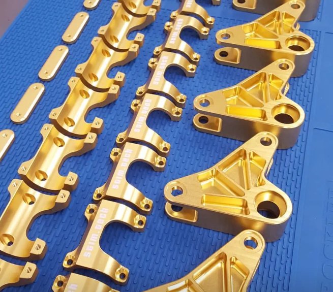
Metal fabrication is the process of converting raw metal stock into functional parts, frames, enclosures, brackets, welded assemblies and finished products. It combines cutting, forming, welding, machining, surface finishing and inspection to create components used in construction, machinery, transportation, energy, electronics, medical equipment and industrial automation.
For buyers, engineers and product teams, the key search intent behind “metal fabrication” is usually practical: understanding what fabrication includes, which process fits a design, what tolerances are realistic, how material choice affects cost, and how to reduce risk before production. This page explains those points from a manufacturing perspective.
What Is Metal Fabrication?
Metal fabrication refers to a group of subtractive, forming and joining operations used to make metal parts from sheet, plate, tube, bar, angle, channel, beam or cast/forged blanks. Unlike simple metal cutting, fabrication often involves multiple steps and may include engineering review, nesting, fixture design, welding procedure development, dimensional inspection and finishing.
A typical fabricated component may begin as flat sheet metal, be laser cut to shape, formed on a press brake, welded into an assembly, ground smooth, powder coated and inspected against a drawing. For heavier work, structural steel fabrication may involve sawing, plasma cutting, drilling, beveling, robotic welding and protective coating.
Custom metal fabrication is especially useful when standard off-the-shelf parts cannot meet a required geometry, load condition, environment, mounting interface or appearance standard.
Common Metal Fabrication Processes
The best fabrication route depends on thickness, material grade, part geometry, required tolerance, batch size, appearance and budget. Many projects combine several of the following processes.
Laser Cutting
Fiber laser cutting is widely used for sheet metal and plate because it offers narrow kerf width, high repeatability and clean edges. It is suitable for stainless steel, mild steel, galvanized steel, aluminum, brass and copper. Typical applications include panels, brackets, machine guards, electrical enclosures, signage, chassis and precision blanks.
Plasma Cutting and Oxy-Fuel Cutting
Plasma cutting is commonly selected for thicker plate where speed and cost efficiency are more important than laser-like edge precision. Oxy-fuel cutting is used mainly for carbon steel plate and heavy structural components. Secondary grinding or machining may be needed when tight edges, weld prep or bearing surfaces are required.
CNC Punching
CNC punching is efficient for sheet metal parts with repeated holes, louvers, countersinks, knockouts, embosses or formed features. It is often competitive for medium to high volumes, especially when the geometry includes many standard features.
Press Brake Bending
Press brake forming bends sheet or plate into angles, channels, boxes, flanges and complex profiles. Bend radius, grain direction, material springback, tooling selection and bend allowance must be considered during design. For accurate results, flat patterns should be developed using the correct K-factor and material data.
Welding and Joining
Fabricated assemblies may use MIG welding, TIG welding, resistance spot welding, laser welding, brazing, riveting, clinching, threaded inserts or mechanical fasteners. Weld selection depends on material, load, heat sensitivity, cosmetic requirements, production volume and applicable standards such as AWS D1.1 for structural steel welding.
Machining After Fabrication
Many fabricated parts require CNC machining after welding or forming. Post-fabrication machining can create accurate mounting holes, bearing surfaces, tapped features, slots, datum faces and sealing surfaces that cannot be held accurately through welding alone.
Surface Finishing
Common finishing options include deburring, grinding, brushing, bead blasting, polishing, passivation, anodizing, zinc plating, hot-dip galvanizing, powder coating, wet painting and e-coating. Finish selection should match corrosion exposure, wear conditions, electrical conductivity, food-contact requirements and visual expectations.
When is laser cutting better than punching?
Laser cutting is usually better for complex contours, short runs, mixed geometries and parts that need high edge quality without dedicated tooling. Punching can be more cost-effective for high-volume sheet metal parts with many repeated holes or formed features such as louvers and embosses.
Materials Used in Metal Fabrication
Material choice affects strength, corrosion resistance, weight, weldability, formability, cost and lead time. A good fabrication supplier should review both the drawing material callout and the actual service environment.
| Material | Common Grades | Typical Advantages | Common Applications |
|---|---|---|---|
| Carbon Steel | A36, A572, 1018, 1045 | High strength, weldable, economical, widely available | Frames, brackets, base plates, structural components, guards |
| Stainless Steel | 304, 316, 430 | Corrosion resistance, clean appearance, good durability | Food equipment, medical carts, tanks, covers, marine hardware |
| Aluminum | 5052, 6061, 6063 | Lightweight, corrosion resistant, machinable, good for enclosures | Aerospace parts, electronics housings, brackets, transportation parts |
| Galvanized Steel | G90, DX51D, SGCC | Improved corrosion protection, economical for outdoor sheet parts | HVAC parts, cabinets, outdoor panels, cable trays |
| Copper and Brass | C110, C260, C360 | Electrical conductivity, thermal conductivity, decorative appearance | Bus bars, terminals, heat-transfer parts, decorative panels |
Stainless steel fabrication often requires special attention to contamination control, heat tint removal and passivation. Using carbon steel tooling or grinding media on stainless parts can introduce iron contamination that may later appear as rust staining.
Typical Tolerances in Fabricated Metal Parts
Fabrication tolerances vary by process, material thickness, part size, machine condition and inspection method. Tighter tolerances are possible, but they should be specified only where functionally necessary because they may require special tooling, secondary machining, fixtures or slower processing.
| Process | Typical Practical Tolerance | Notes |
|---|---|---|
| Laser cutting, sheet metal | ±0.10 mm to ±0.25 mm | Depends on thickness, machine calibration and cut geometry |
| Plasma cutting, plate | ±0.75 mm to ±1.50 mm | Edge taper and heat input are greater than laser cutting |
| Press brake bending | ±0.5° to ±1.0°; flange length often ±0.25 mm to ±0.75 mm | Springback, bend sequence and tooling affect consistency |
| Welded assemblies | ±1.0 mm to ±3.0 mm or more | Heat distortion and fixture design strongly influence results |
| Post-fabrication CNC machining | ±0.01 mm to ±0.05 mm | Used for precision holes, datums and critical interfaces |
For complex assemblies, dimensional requirements should be tied to functional datums. Applying tight tolerances to every feature may increase cost without improving performance. A better approach is to identify the mating surfaces, mounting holes, sealing planes and load-bearing interfaces that truly control function.
Design for Manufacturability in Metal Fabrication
Design for manufacturability, often called DFM, reduces scrap, rework, welding distortion and lead time. It also helps ensure that the fabricated part can be produced consistently at prototype, pilot and production volumes.
- Use inside bend radii that match available tooling and material thickness.
- Keep holes away from bend lines to prevent stretching or deformation.
- Specify realistic tolerances based on process capability, not only CAD precision.
- Use slots or tabs for self-locating weldments where assembly accuracy matters.
- Avoid unnecessary full-penetration welds if fillet welds meet strength requirements.
- Confirm coating buildup on threaded holes, slots, hinges and mating surfaces.
- Use standard material thicknesses and grades to reduce procurement delays.
- Plan drain holes and vent holes for galvanizing, plating or powder coating.
Sheet metal fabrication benefits from early flat-pattern review. A part that looks simple in 3D may be difficult to bend if flanges collide with press brake tooling or if the bend sequence traps the part.
Example: reducing distortion in a welded frame
A machine base frame made from 6 mm carbon steel plate showed up to 4.8 mm diagonal distortion after welding. By changing the weld sequence, adding temporary restraint fixtures and replacing continuous non-critical welds with intermittent fillet welds, final distortion was reduced to 1.6 mm. Post-weld machining time dropped by approximately 28% because less material had to be removed from datum pads.
Quality Control and Inspection
Quality control in metal fabrication should begin before cutting material. Drawing review, material verification, weld procedure planning, first article inspection and final inspection all reduce the risk of nonconforming parts.
Material Verification
Material test reports, heat numbers and positive material identification may be required for regulated industries. For stainless steel, chemical composition and surface condition are often important for corrosion performance.
Dimensional Inspection
Inspection tools may include calipers, micrometers, height gauges, angle gauges, thread gauges, coordinate measuring machines, laser trackers and custom go/no-go fixtures. For production work, first article inspection confirms that the fabrication route matches the engineering drawing before full batch release.
Weld Inspection
Weld quality may be evaluated visually or by non-destructive testing methods such as dye penetrant testing, magnetic particle testing, ultrasonic testing or radiographic testing. Critical weldments may require qualified welders, documented welding procedure specifications and traceable inspection records.
Finish Inspection
Surface finish inspection may include coating thickness measurement, adhesion testing, salt spray testing, gloss measurement, roughness checks and visual acceptance criteria. The correct acceptance standard should be defined before production, especially for visible consumer or architectural parts.
Traceability becomes important when fabricated metal parts are used in lifting equipment, pressure-related systems, transportation, medical devices or safety-critical machinery.
Real Engineering Problems and Measurable Improvements
Fabrication decisions have measurable effects on cost, quality and product life. The following examples show how process review can change project outcomes.
| Problem | Root Cause | Engineering Change | Measured Result |
|---|---|---|---|
| Powder coated brackets failed hole alignment after coating | Coating buildup reduced clearance in mounting holes | Increased hole diameter by 0.30 mm and masked threaded features | Assembly rework reduced from 12% to below 2% |
| Aluminum enclosure covers warped after welding | Excessive heat input and continuous welds on thin sheet | Changed to stitch welds, added fixture cooling and revised weld sequence | Flatness improved from 3.2 mm to 0.9 mm over 500 mm length |
| Laser-cut stainless panels showed rust stains outdoors | Cross-contamination from carbon steel grinding tools | Separated stainless finishing tools and added passivation | Field staining complaints eliminated in the next production batch |
| High scrap rate on bent sheet metal part | Hole pattern too close to bend line | Moved holes 1.5 material thicknesses away from bend tangent | Scrap reduced from 9.5% to 1.8% |
These examples demonstrate why fabrication should not be treated as a commodity cutting service only. Process planning, tooling decisions, weld design and finishing control can materially affect downstream assembly and field performance.
Applications of Metal Fabrication
Metal fabrication supports both light-gauge sheet metal products and heavy-duty structural assemblies. Common applications include:
- Electrical enclosures, control cabinets and server rack components
- Machine frames, guards, brackets, bases and automation structures
- Architectural metalwork, handrails, stairs, panels and canopies
- HVAC ductwork, plenums, housings and ventilation components
- Material handling carts, conveyors, platforms and mezzanine components
- Food processing equipment, stainless tables, hoppers and tanks
- Automotive, rail, marine and aerospace support components
- Renewable energy brackets, battery trays and power distribution parts
Precision metal fabrication is increasingly important for robotics, EV infrastructure, semiconductor equipment and medical device manufacturing, where fit, repeatability and documentation can be as important as raw strength.
Cost Drivers in Metal Fabrication
The cost of fabricated metal parts is influenced by material utilization, cutting time, bend count, weld length, inspection requirements, finishing, packaging and order volume. Design choices can increase or reduce cost significantly.
- Thicker material increases cutting time, machine power requirements and part weight.
- Long continuous welds add labor, consumables, distortion risk and inspection time.
- Non-standard material grades may increase lead time and minimum order quantity.
- Tight cosmetic requirements may require extra grinding, polishing or masking.
- Small batches may carry higher unit cost because programming and setup are spread over fewer parts.
- Assemblies with poor access for welding or finishing may require special fixtures or process changes.
Cost reduction should not mean weakening the part. A more effective method is to match each feature to its function: precision where needed, standard tolerance where acceptable, and process-friendly geometry throughout the design.
How drawings affect fabrication cost
Clear drawings reduce quoting uncertainty and production risk. A useful fabrication drawing should include material grade, thickness, finish, critical dimensions, general tolerances, weld symbols, thread specifications, grain direction if needed, inspection criteria and revision control. STEP files are helpful, but they should not replace controlled 2D drawings for tolerances and manufacturing notes.
How to Select a Metal Fabrication Supplier
Selecting a supplier should involve more than comparing unit price. A capable fabrication partner should be able to review drawings, identify manufacturability issues, control process variation and provide consistent documentation.
- Process capability: laser cutting, bending, welding, machining and finishing capacity
- Material experience: carbon steel, stainless steel, aluminum and specialty alloys
- Quality system: inspection plans, calibration, traceability and nonconformance control
- Engineering support: DFM review, fixture planning and tolerance analysis
- Welding capability: qualified welders, procedure control and applicable standards
- Production scalability: prototype support plus repeatable batch manufacturing
- Finishing control: coating thickness, masking, corrosion protection and packaging
- Communication: revision management, lead-time visibility and technical feedback
Metal fabrication services deliver the best results when design intent, process capability and inspection requirements are aligned before production starts.
Key Takeaways
Metal fabrication covers a wide range of processes, from laser cutting and press brake bending to welding, machining and surface finishing. The strongest projects begin with manufacturable design, suitable material selection, realistic tolerances and documented quality control.
For engineered products, fabricated metal parts should be evaluated by function: how they carry load, how they fit with mating components, how they resist corrosion, how they are assembled and how they will be inspected. When these factors are considered early, fabrication can deliver durable, repeatable and cost-effective components for both prototype and production use.