
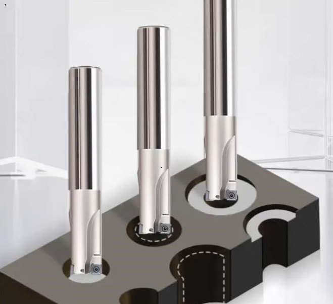
Metal broaching is a precision machining process that removes material with a multi-tooth cutting tool called a broach. Each tooth is slightly taller or differently shaped than the previous tooth, so the tool progressively cuts a profile in one controlled stroke. Broaching is widely used for internal keyways, splines, square holes, serrations, firearm components, turbine slots, gears, automotive transmission parts, hydraulic components and high-volume precision metal parts.
The process is especially valuable when a part requires a repeatable profile, tight dimensional control and short cycle time. Compared with milling, shaping, wire EDM or slotting, broaching can produce complex forms in seconds when the tool and fixture are correctly engineered. However, broaching is tool-specific, so it is most economical when production volume, geometry stability and material behavior justify the custom broach investment.
What Is Metal Broaching?
Broaching is a linear or rotary cutting operation in which a toothed tool removes material in a predetermined sequence. A typical broach has three functional tooth zones: roughing teeth, semi-finishing teeth and finishing teeth. The roughing section removes most of the stock, the semi-finishing section stabilizes the profile, and the finishing section controls size, geometry and surface finish.
Unlike drilling or milling, where the same cutting edge repeatedly removes chips, a broach distributes cutting load across many teeth. This allows high repeatability, but it also means that broach geometry, rake angle, tooth rise, pitch, gullet capacity, pull force and lubrication must be matched to the workpiece material.
| Parameter | Common Range | Engineering Notes |
|---|---|---|
| Tooth rise per tooth | 0.01–0.08 mm | Lower values for hard alloys and fine finishes; higher values for softer steels or nonferrous metals |
| Dimensional tolerance | ±0.0125–±0.05 mm | Depends on part rigidity, tool wear, fixture alignment and heat treatment condition |
| Surface finish | Ra 0.8–3.2 µm | Finer finishes are possible with sharp finishing teeth, correct coolant and stable fixturing |
| Cycle time | 5–60 seconds | Short strokes and production broaching machines can be significantly faster |
| Suitable production volume | Medium to high | Custom tooling cost is usually justified by repeatability and low per-part cycle time |
Main Types of Metal Broaching Processes
The best broaching method depends on whether the feature is internal, external, blind, through, shallow, deep, symmetrical or interrupted. The following process types are commonly used in manufacturing.
Internal Broaching
Internal broaching cuts features inside a pre-existing hole or bore. Typical applications include keyways, splines, involute forms, hexagonal holes, square holes and internal serrations. A pilot hole is normally drilled, bored or reamed before broaching to provide accurate tool entry and chip clearance.
External or Surface Broaching
Surface broaching removes material from an outside face. It is used for flats, slots, gear teeth, bearing cap surfaces, turbine root forms and connecting rod features. Surface broaching can be highly productive because multiple surfaces may be cut in one machine stroke.
Keyway Broaching
Keyway broaching forms straight internal slots for keys in pulleys, gears, couplings and hubs. It often uses a bushing to guide the broach and shims to progressively increase depth. Keyway dimensions are commonly checked against standards such as ASME B17.1, DIN 6885 or ISO key and keyseat conventions depending on the market.
Spline Broaching
Spline broaching produces internal or external splines for torque transmission. It is used in automotive shafts, clutch hubs, power tools, hydraulic pumps and aerospace drive systems. Common reference systems include involute spline standards such as ANSI B92.1 and DIN 5480, as well as straight-sided spline specifications such as ISO 14.
Rotary Broaching
Rotary broaching, also called wobble broaching, is often used on CNC lathes and Swiss-type machines to create polygons, hex sockets, Torx-like forms and small serrations. The tool is held at a slight angle and rotates synchronously with the workpiece, gradually forming the shape. It is useful for smaller features but is not the same as long-stroke production broaching.
How the Broaching Process Works
- Pre-machining: The workpiece is drilled, bored, turned, milled or heat treated to establish the required starting geometry.
- Fixturing: The part is located against a datum surface so that the broached profile is aligned with functional features.
- Tool entry: The broach is guided into the bore, slot or surface path. For internal broaching, a puller may attach to the broach end.
- Cutting stroke: The broach moves through the part. Each tooth removes a controlled amount of metal, typically 0.01–0.08 mm per tooth, depending on material and tool design.
- Chip evacuation: Chips curl into gullets between teeth. Correct gullet volume is essential to avoid tool jamming and profile damage.
- Finishing: Final teeth size the feature and improve surface finish. Burnishing sections may be used for some ductile materials.
- Inspection: The part is checked for size, form, burrs, surface finish, parallelism, concentricity or spline fit.
In production, the broaching stroke may be powered by a hydraulic broaching machine, electromechanical drive, vertical broach press, horizontal broach machine, CNC broaching attachment or rotary broaching holder. Machine selection affects stroke length, speed control, pull force capacity, part loading time and process stability.
Broaching Tolerances, Surface Finish and Accuracy
Broaching is known for repeatable sizing because the tool geometry defines the final profile. For well-fixtured steel components, dimensional tolerance of ±0.0125 to ±0.025 mm is achievable in many production cases. General commercial broaching tolerances may be wider, especially for long keyways, thin-wall parts, interrupted cuts or heat-treated components.
Surface finish is also predictable when the broach is sharp and chips are controlled. A typical broached surface finish is Ra 0.8–3.2 µm. Finer finishes usually require optimized rake angle, cutting oil, finishing tooth geometry, stable workholding and controlled material hardness.
| Factor | Effect on Part Quality | Control Method |
|---|---|---|
| Tool wear | Oversize, taper, poor finish, burr growth | Scheduled sharpening, tool life tracking and coating selection |
| Workpiece hardness variation | Uneven cutting load and dimensional drift | Specify hardness range and verify heat treatment consistency |
| Fixture alignment | Angular error, profile shift or non-concentric splines | Use precision datums, hardened guides and repeatable clamping |
| Chip control | Scoring, tooth breakage and tool jamming | Design adequate gullet capacity and use high-lubricity cutting fluid |
| Part rigidity | Wall distortion and springback | Support thin sections and reduce tooth rise when required |
Metals Suitable for Broaching
Many metals can be broached successfully, but tool geometry and cutting fluid must match the material. Ductile materials may smear or build up on the cutting edge, while hard alloys increase cutting force and shorten tool life. The following materials are commonly broached:
- Carbon steel: Very common for keyways, gears, hubs and mechanical drive parts.
- Alloy steel: Suitable for splines, transmission components and high-strength parts when hardness is controlled.
- Stainless steel: Broachable, but prone to work hardening; sharp tools and high-lubricity oil are important.
- Cast iron: Cuts well but is abrasive; tool wear monitoring is important.
- Aluminum: Easy to cut but can gall; polished tools and suitable coolant reduce built-up edge.
- Brass and bronze: Often broach cleanly, but tooth geometry should prevent grabbing in free-machining alloys.
- Titanium and nickel alloys: Possible in specialized applications, but force, heat and tool wear become limiting factors.
For hardened steel, broaching is usually performed before final hardening unless the feature requires hard broaching with specialized carbide or coated tooling. Many production parts are rough machined, broached in the annealed or normalized state, then heat treated and finish ground where necessary.
Broach Tool Design and Cutting Parameters
A broach is not a generic cutter; it is a custom-engineered tool. Its performance depends on tooth pitch, rake angle, clearance angle, tooth rise, land width, chip breaker pattern, gullet depth, tool material and coating. High-speed steel broaches remain common, while powder metallurgy HSS, carbide sections and PVD coatings are used when wear resistance or high-volume production justifies the cost.
The most important tool design constraint is chip volume. If the gullet cannot hold the chip generated by each tooth, chips compact inside the cut, causing scoring, force spikes or broken teeth. For deep internal broaching, chip length and curl behavior must be evaluated early in the design stage.
| Tool Element | Function | Design Consideration |
|---|---|---|
| Pull end or shank | Connects the tool to the broaching machine | Must withstand total pull force with safety margin |
| Front pilot | Guides tool entry | Should fit the pre-machined bore without excessive clearance |
| Roughing teeth | Remove most material | Require adequate chip space and controlled tooth rise |
| Semi-finishing teeth | Stabilize form before final sizing | Reduce cutting load variation |
| Finishing teeth | Establish final profile | Need precise grinding and careful wear monitoring |
| Rear pilot | Supports tool exit | Helps reduce bellmouth and exit-side damage |
Engineering note: estimating broach pull force
A simplified approach is to estimate force from chip area, number of teeth cutting simultaneously and material-specific cutting resistance. The exact value depends on rake angle, lubrication, edge condition and chip formation. In practical tool design, engineers add a safety margin because load can rise sharply when chips pack or hardness varies. For long internal splines and difficult alloys, machine capacity should be reviewed before tool release.
Design for Manufacturability in Broached Metal Parts
Design decisions made before quoting can determine whether broaching is economical and stable. The key principle is to give the broach a clear path, a rigidly supported part and enough stock consistency for predictable cutting. Good fixture rigidity is often as important as the broach itself.
- Provide a straight through-path whenever possible; blind broaching is more complex and may require special tooling.
- Control pilot hole diameter, roundness and location before internal broaching.
- Avoid thin unsupported walls next to heavy cuts because broaching force can distort the part.
- Specify functional tolerances instead of unnecessarily tight general tolerances.
- Allow burr clearance on exit edges or specify deburring requirements separately.
- Use generous lead-in features where possible to improve tool entry.
- Confirm whether heat treatment occurs before or after broaching.
- For splines, define major diameter, minor diameter, tooth thickness, class of fit and inspection method.
For internal keyways, the relationship between bore diameter, keyway width and hub length should be checked early. Long keyways in small bores increase tool slenderness and deflection risk. For splines, concentricity to bearing journals or datum bores often matters more than the spline size itself, so fixturing strategy should reflect the functional assembly.
Real Engineering Issues and Measured Process Improvements
In production broaching, quality problems usually arise from a combination of material variation, tool wear, inadequate chip control or unstable fixturing. The following examples show typical corrective actions and measurable results seen in industrial machining environments.
| Application | Problem | Root Cause | Corrective Action | Measured Result |
|---|---|---|---|---|
| 4140 steel internal spline, 28–32 HRC | Exit burrs and inconsistent tooth thickness | Finishing teeth worn and part not fully supported near exit | Added exit support ring and reduced sharpening interval | Burr height reduced by 45%; spline tooth variation reduced from 0.038 mm to 0.018 mm |
| Aluminum hub keyway | Scored slot walls | Built-up edge from inadequate lubrication | Changed to higher-lubricity oil and polished broach lands | Average surface finish improved from Ra 3.6 µm to Ra 1.4 µm |
| Cast iron surface broaching | Short tool life | Abrasive material and excessive tooth load | Adjusted tooth rise and added coated tool section | Tool life increased by approximately 20–35% between sharpenings |
| Stainless steel hex broaching | Oversize form after 2,000 parts | Work hardening and edge rounding | Reduced speed, increased oil flow and tracked edge wear | Dimensional drift reduced by 50% over the next production lot |
These results are not universal guarantees, but they illustrate the practical nature of broaching optimization. Small changes to support, lubrication, tooth geometry or maintenance frequency can produce significant improvements in part quality and tool cost.
When metal broaching may not be the best process
Broaching is usually not the first choice for very low-volume prototypes, frequently changing profiles, extremely hard materials, deep blind cavities with no chip exit, or parts that cannot tolerate cutting force. In those cases, CNC milling, slotting, shaping, wire EDM, laser machining or additive manufacturing may be more practical.
Broaching vs. Milling, Shaping, EDM and Slotting
Process selection depends on volume, geometry, tolerance, material and tooling budget. Broaching often has a higher initial tool cost but lower cycle time. Milling and EDM are more flexible but may be slower for repeated internal profiles.
| Process | Best For | Advantages | Limitations |
|---|---|---|---|
| Metal broaching | Repeated keyways, splines, slots and shaped profiles | Fast cycle time, repeatable profile, good finish | Custom tool cost, limited flexibility |
| CNC milling | Flexible profiles, prototypes and lower volume | Programmable, widely available, no dedicated broach required | Longer cycle time for some internal forms |
| Wire EDM | Hard metals and intricate through-profiles | No cutting force, high accuracy | Slower and limited to electrically conductive materials |
| Slotting or shaping | Internal slots and low-volume keyways | Lower tooling cost for simple features | Slower stroke-by-stroke material removal |
| Rotary broaching | Small polygonal holes on lathes | Can run in CNC turning setup | Limited depth, size and profile complexity |
Quality Control and Inspection for Broached Features
Inspection methods should match the functional requirement of the broached feature. A keyway may only require width, depth and angular position checks, while an involute spline may require go/no-go gauges, roll measurement, CMM inspection or analytical spline measurement. For safety-critical components, inspection plans should include first-article approval, tool wear monitoring and traceability of material hardness.
- Keyways: Measure width, depth, straightness, angular orientation and burr condition.
- Splines: Check major diameter, minor diameter, effective tooth thickness, profile form and fit class.
- Surface-broached parts: Verify flatness, parallelism, step height, surface finish and datum relationship.
- Internal polygons: Use plug gauges, optical measurement or CMM scanning depending on tolerance.
- Tool condition: Track number of parts between sharpenings, cutting load changes and surface finish trends.
Monitoring broach pull force can also help detect process drift. A gradual force increase may indicate tool wear, while sudden force spikes often suggest chip packing, hardness variation, misalignment or lubrication failure.
Inspection note: why go/no-go gauges are common in spline broaching
Production spline features are often controlled by functional fit rather than isolated tooth dimensions. Go/no-go gauges quickly verify whether the broached spline will assemble with its mating component. For development, failure analysis or high-accuracy applications, gauge inspection may be supplemented by CMM or dedicated spline measurement equipment.
Common Broaching Defects and Prevention
Most broaching defects are preventable when the tool, workpiece, machine and cutting fluid are treated as a single system. The table below summarizes frequent defects and corrective actions.
| Defect | Likely Cause | Prevention |
|---|---|---|
| Oversize feature | Tool wear, misalignment or excessive heat | Inspect finishing teeth, improve guidance and control cutting fluid flow |
| Tapered keyway or spline | Part movement, tool deflection or uneven support | Improve fixture support and verify datum contact |
| Chatter marks | Insufficient rigidity or unsuitable tooth pitch | Increase support, review machine condition and adjust tool design |
| Scoring | Chip drag or built-up edge | Improve lubrication, chip space and tool surface finish |
| Broken broach teeth | Excessive load, hard spot or chip compaction | Verify material hardness, reduce tooth rise and prevent chip packing |
| Heavy burrs | Dull finishing teeth or unsupported exit | Sharpen tool, add backup support and specify deburring operation |
Cost Drivers in Metal Broaching
Broaching cost is influenced by both tooling and production economics. A custom broach can be expensive, but the cost per part can be very low when the tool runs thousands or millions of cycles. The most important cost drivers are profile complexity, broach length, tool material, coating, tolerance class, part material, required inspection and expected tool life.
- Tooling cost: Increases with complex splines, long profiles, tight tolerances and special coatings.
- Machine time: Usually low per part, especially in dedicated production broaching.
- Setup cost: Depends on fixture complexity, alignment requirements and part handling.
- Tool maintenance: Includes sharpening, recoating, dimensional verification and tool storage.
- Scrap risk: Higher when broaching occurs late in the manufacturing route after expensive prior operations.
For purchasing and engineering teams, the best evaluation is not tool price alone. A complete cost model should compare tooling amortization, cycle time, inspection burden, scrap rate, expected sharpenings, machine availability and whether the broached feature reduces secondary operations.
Key Takeaways for Engineers and Buyers
Metal broaching is one of the most efficient methods for producing repeatable internal and external profiles in metal components. It is particularly strong for high-volume keyways, splines, serrations and formed slots where cycle time, dimensional repeatability and surface finish matter. The process performs best when the part is designed for a clear tool path, stable fixturing, controlled hardness and reliable chip evacuation.
The most successful broaching projects define the functional feature clearly, select the correct process type, verify machine force capacity, engineer the broach for the material and establish an inspection plan before production. When these factors are aligned, broaching can deliver fast throughput, consistent geometry and competitive per-part cost for precision metal manufacturing.