
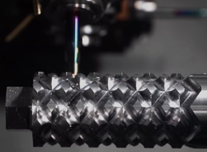
Hastelloy CNC machining is a specialized discipline that bridges the gap between advanced material science and high-precision manufacturing. While generic machining guides provide a starting point, achieving consistent success with Hastelloy requires a deep, integrated understanding of its unique metallurgical behavior and the corresponding CNC process adaptations. This comprehensive guide moves beyond isolated tips to present a complete, systematic workflow for machining Hastelloy components, covering planning, programming, execution, and validation, backed by data-driven insights to avoid common pitfalls and ensure part integrity.
1. Pre-Machining Planning and Feasibility Analysis
Success in Hastelloy CNC machining is determined long before the first tool touches the blank. A thorough feasibility analysis is critical. This starts with material certification and blank conditioning. Verify the alloy grade (e.g., C-276, C-22, B-2) and its heat treatment condition (typically solution-annealed). Forging or rolled bar stock may have residual stresses; consider a stress-relief cycle for complex, thin-walled parts to prevent distortion. Next, analyze the part geometry. Identify deep pockets, thin ribs, and high aspect-ratio features that are challenging in any material but become high-risk with Hastelloy's tendency to work harden and vibrate. Use this analysis to define fixturing strategy, tool access, and the sequence of operations (roughing, semi-finishing, stress-relief, finishing).
Critical pre-machining checklist for Hastelloy
- Material Certification: Confirm grade, heat treatment, and mill test report.
- Blank Stress State: Plan for pre-machining stress relief if needed.
- Fixturing Design: Ensure rigidity and access; plan for re-fixturing steps.
- Toolpath Simulation: Run full simulation to check for tool deflection, collisions, and air cutting.
- Coolant System Check: Verify high-pressure pump (70+ bar) and through-spindle capability.
2. Machine Tool Selection and Setup for Optimal Rigidity
Not all CNC machines are suitable for Hastelloy. The ideal machine exhibits high static and dynamic rigidity, thermal stability, and ample torque at lower RPMs. Look for a machine with a box-way or heavy linear guide construction, a geared headstock for high torque, and a coolant system capable of high pressure and high flow. During setup, use the most rigid tool holders available (e.g., hydraulic chucks or shrink-fit over collet chucks) to minimize runout and vibration. Workholding must be absolutely secure; consider custom fixtures, serrated jaw inserts, or vacuum plates to maximize clamping force and dampen vibrations. A dial indicator should be used to confirm part runout is within 0.02 mm after clamping.
3. The Integrated Cutting Strategy: Tools, Parameters, and Paths
This is the core execution phase where planning meets the cut. The strategy must be cohesive:
- Tooling: Use dedicated, sharp tools with positive geometry. For roughing, robust round inserts or variable-pitch end mills distribute load. For finishing, fine-grain carbide ball end mills or wiper inserts are key for surface quality.
- Parameters: Adhere to the low-speed, high-feed, adequate depth-of-cut doctrine. Example: For side milling C-276 with a 10mm carbide end mill, use 800 RPM (~25 m/min), 500 mm/min feed, 1mm axial depth, and 0.5mm radial stepover.
- Toolpaths: Employ modern high-efficiency milling (HEM) or trochoidal paths to maintain constant chip load and radial engagement below 10-15%. This keeps cutting forces steady, manages heat, and extends tool life. Avoid full-width slotting and conventional zig-zag paths that cause thermal shock.
Field data shows that integrating HEM toolpaths with optimized parameters can increase metal removal rates by 20-30% while reducing tool wear compared to conventional methods.
4. In-Process Monitoring and Adaptive Control
Real-time monitoring is essential for process stability and defect prevention. Use the machine's spindle load monitor to establish a baseline power consumption during a stable cut. Significant deviations (>15%) indicate tool wear, chip packing, or a change in material condition. For critical operations, implement on-machine probing. A touch probe can be used after semi-finishing to measure the part, and the CNC program can then compensate for observed thermal growth or springback before the final finishing pass. This adaptive control is often the difference between a part that scrapes by tolerance and one that is consistently precise.
5. Post-Machining: Deburring, Cleaning, and Surface Treatment
The final part quality and corrosion resistance are secured here. Deburr using non-ferrous tools (carbide, ceramic) to prevent iron contamination. A meticulous cleaning process is non-negotiable: use ultrasonic cleaning or high-pressure spray with a non-chlorinated, alkaline cleaner to remove all coolant, oil, and microscopic chips. For parts requiring maximum corrosion performance, especially after extensive machining or welding, a passivation treatment in a nitric acid bath is performed to dissolve surface iron contaminants and reform the uniform, protective chromium oxide layer. Final inspection should include dimensional verification, surface roughness measurement (Ra, Rz), and for highly stressed components, fluorescent penetrant inspection to check for micro-cracks.
Conclusion: A Disciplined, End-to-End System
Hastelloy CNC machining is not merely a set of altered cutting parameters; it is a comprehensive, disciplined manufacturing system. From informed pre-planning and rigid machine setup to an integrated cutting strategy, real-time process control, and careful post-processing, each stage is interdependent. By adopting this holistic, systematic approach, manufacturers can reliably produce high-integrity Hastelloy components that meet the stringent demands of critical applications in aerospace, chemical processing, and energy, transforming a challenging material into a consistent and competitive advantage.