
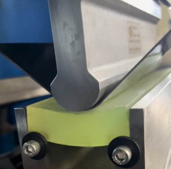
Metal bending is a forming process that plastically deforms sheet metal, plate, tube, bar or profile stock into a required angle or radius without removing material. It is used to manufacture brackets, enclosures, chassis, panels, frames, clips, covers, electrical cabinets, HVAC parts, automotive components and structural assemblies.
For engineers, buyers and manufacturers, the search intent behind metal bending is usually practical: how the process works, which bending method to choose, how to calculate flat patterns, what tolerances are realistic, and how to avoid cracks, springback, wrong flange lengths or tooling conflicts. This guide focuses on production-ready information used in sheet metal fabrication and press brake bending.
What Is Metal Bending?
Metal bending changes the shape of a workpiece by applying force around a bend line. The outside surface of the bend is stretched, the inside surface is compressed, and a neutral axis between them changes length very little. In sheet metal bending, this neutral axis location is expressed by the K-factor and is essential for accurate bend allowance and flat pattern development.
Unlike cutting or machining, bending is a chipless manufacturing process. It preserves material continuity, but the final result depends heavily on material grade, thickness, tensile strength, grain direction, tooling geometry, bend radius, machine repeatability and operator setup.
Common Metal Bending Methods
Different bending methods are selected according to part geometry, thickness, required accuracy, batch size and tooling cost. The most common industrial methods include press brake bending, roll bending, tube bending, panel bending and rotary draw bending.
| Method | Typical Use | Key Advantages | Limitations |
|---|---|---|---|
| Press brake bending | Sheet metal brackets, covers, panels, enclosures | Flexible, accurate, low tooling cost for many geometries | Requires correct punch and die clearance; limited by flange collisions |
| Air bending | General sheet metal fabrication | Versatile angles with one die opening; lower tonnage | More sensitive to springback and material variation |
| Bottoming | Higher repeatability angle control | Better angle consistency than air bending | Higher forming force; tool angle must match final angle |
| Coining | Precision small bends and reduced springback | Excellent angle control and sharp bends | Very high tonnage; may thin or mark material |
| Roll bending | Cylinders, cones, large-radius curved panels | Good for large radii and long parts | Less suitable for tight 90-degree flanges |
| Rotary draw tube bending | Tubes, handrails, frames, exhaust pipes | Controls ovality and wrinkle formation | Requires tube-specific tooling and mandrels for tight bends |
Press Brake Bending: How the Process Works
Press brake bending is the dominant process for sheet metal bending. A punch pushes the material into a V-die or other die shape, creating a controlled bend angle. CNC press brakes use back gauges, ram position control and programmed bend sequences to produce repeatable formed parts.
Air Bending
In air bending, the sheet contacts the punch tip and the two shoulders of the V-die. The punch does not force the material fully to the bottom of the die. Angle is controlled mainly by punch penetration. Air bending is efficient and flexible, but the final angle is influenced by springback, yield strength and thickness variation.
Bottoming
In bottoming, the punch pushes the sheet closer to the die angle. This increases contact and reduces angle variation compared with air bending. It is useful for repeatable production, but requires higher tonnage and tooling that closely matches the desired bend angle.
Coining
Coining compresses the material intensely at the bend area, plastically deforming it through the thickness. It produces minimal springback and accurate angles, but demands much higher press force and may leave visible tooling marks. It is less common for general fabrication because air bending can achieve good results with modern CNC controls.
When should air bending be used instead of coining?
Air bending is usually preferred when the shop needs flexibility across different angles, lower forming tonnage and reduced tooling cost. Coining is better reserved for precision bends where springback must be minimized and the machine has enough capacity for the required tonnage.
Important Terms in Metal Bending
Accurate bending depends on shared terminology between design, estimating, programming, tooling and inspection teams.
- Bend line: The line along which the workpiece is bent.
- Inside bend radius: The radius measured on the compressed inside surface of the bend.
- Outside bend radius: The radius measured on the stretched outside surface.
- Material thickness: The sheet or plate thickness, often represented as t.
- Bend angle: The included or formed angle after bending, depending on drawing convention.
- K-factor: The ratio of neutral axis location to material thickness.
- Bend allowance: The arc length of the neutral axis through the bend.
- Bend deduction: The amount subtracted from outside flange dimensions to calculate flat length.
- Setback: The distance from the bend tangent point to the mold line intersection.
- V-die opening: The width of the die opening that supports the material during press brake bending.
- Minimum flange length: The shortest flange that can be safely formed without slipping into the die.
Bend Allowance, Bend Deduction and K-Factor
Flat pattern accuracy is one of the most important reasons to understand bending calculations. A formed part that looks simple can fail assembly if the flat blank is developed with the wrong bend allowance.
Bend Allowance Formula
The common bend allowance formula for sheet metal is:
BA = A × π / 180 × (R + K × T)
Where BA is bend allowance, A is bend angle in degrees, R is inside bend radius, K is K-factor, and T is material thickness.
Typical K-Factor Ranges
| Forming Condition | Approximate K-Factor | Notes |
|---|---|---|
| Sharp bend, tight radius | 0.30 to 0.35 | Neutral axis shifts toward the inside surface |
| Typical air bend | 0.38 to 0.45 | Common starting range for many fabrication jobs |
| Large radius bend | 0.45 to 0.50 | Neutral axis moves closer to the center of thickness |
These values are starting points, not universal constants. Production shops often create bend tables based on their specific press brake, material supplier, punch radius, die opening and inspection data. A validated bend table can reduce first-article corrections and improve repeatability across operators and machines.
Why can two shops get different flat patterns for the same drawing?
Two shops may use different tooling, V-die openings, punch nose radii, material batches and bending methods. These variables change the actual inside radius and neutral axis position, so their bend allowance and bend deduction values may differ even when the final drawing dimensions are identical.
Material Behavior: Springback, Grain Direction and Bend Radius
Metals do not remain exactly where the punch leaves them. After unloading, elastic recovery causes the bend angle to open slightly. This is called springback. High-strength steels, stainless steels and aluminum alloys usually spring back more than mild steel.
The inside bend radius should be selected according to ductility and thickness. A radius that is too small can create cracking on the outside surface, especially when bending across an unfavorable grain direction. For many low-carbon steel parts, an inside radius near 1t is practical. For harder aluminum or stainless steel, larger radii may be required.
| Material | Common Minimum Inside Radius | Manufacturing Note |
|---|---|---|
| Low-carbon steel | 0.5t to 1t | Good ductility; widely used for brackets and enclosures |
| Stainless steel 304 | 1t to 2t | Higher springback and work hardening than mild steel |
| Aluminum 5052-H32 | 1t to 1.5t | Good formability for sheet metal parts |
| Aluminum 6061-T6 | 2t to 4t or more | More crack-sensitive; temper and bend direction are critical |
| Galvanized steel | 1t or more | Coating damage and die marks should be considered |
Grain direction matters because rolled sheet has directional properties. Bending parallel to the grain increases crack risk, while bending perpendicular to the grain usually improves formability. Critical parts should specify grain direction when purchasing material or nesting blanks.
Press Brake Tooling and Machine Parameters
Tooling selection directly affects bend radius, tonnage, flange length, surface quality and part accuracy. The punch nose radius, punch angle, V-die opening, die shoulder radius and tool height all influence the forming result.
V-Die Opening
A common starting point for air bending mild steel is a V-die opening about 6 to 8 times material thickness. Thin materials may use a smaller ratio, while thick plates or high-strength materials may need larger openings to reduce tonnage and marking.
Bending Tonnage
Tonnage must be checked before production. Excessive force can damage tooling, overload the press brake or create unsafe conditions. Required tonnage increases with material tensile strength, thickness squared and bend length. Stainless steel can require approximately 1.5 times the force of mild steel, while some high-strength steels require far more.
Minimum Flange Length
The flange must be long enough to sit on the die shoulders during bending. If the flange is too short, it may slip into the die opening, causing inconsistent angles or unsafe forming. In many air bending setups, minimum flange length is roughly 0.7 times the V-die opening, but actual values depend on tooling and material.
What happens if the selected V-die is too small?
A small V-die opening can reduce the inside bend radius and allow short flanges, but it increases forming tonnage and the risk of tooling marks, cracking and press overload. It may also create a sharper bend than the material can tolerate.
Design Guidelines for Manufacturable Bent Metal Parts
Design for manufacturability reduces rework, scrap and quotation uncertainty. The following guidelines are commonly used for sheet metal bending and press brake fabrication.
- Keep inside bend radii consistent across the part when possible to reduce tool changes.
- Avoid placing holes, slots or cutouts too close to the bend line unless deformation is acceptable.
- Use bend reliefs at the ends of flanges to prevent tearing or distortion.
- Specify dimensions from one functional datum instead of chaining many flange dimensions.
- Allow realistic angular tolerance, often ±0.5° to ±1.0° for many press brake parts, depending on material and setup.
- Consider hardware insertion, welding, powder coating and assembly access after bending.
- Use larger bend radii for brittle materials, hard tempers or visible cosmetic surfaces.
- Check whether the part can be bent in sequence without tool or machine collisions.
- Account for coating thickness if tight fits or electrical grounding surfaces are required.
For tight tolerance projects, it is better to define critical-to-function dimensions after forming instead of relying only on flat pattern dimensions. This approach aligns inspection with the final assembled condition.
Typical Tolerances and Quality Expectations
Metal bending tolerance depends on part size, material, thickness, tooling, bend length and inspection method. A short flange in thin aluminum may hold tighter dimensional repeatability than a long stainless steel flange with multiple bends.
| Feature | Typical Commercial Range | Factors Affecting Result |
|---|---|---|
| Bend angle | ±0.5° to ±1.0° | Springback, tooling, operator setup, material variation |
| Flange length | ±0.25 mm to ±0.75 mm | Back gauge accuracy, blank size, bend sequence |
| Overall formed size | ±0.5 mm to ±1.5 mm | Accumulated bends, part length, inspection datum |
| Inside radius | Tooling-dependent | Punch radius, V-die opening, material strength |
| Flatness after bending | Application-dependent | Residual stress, bend layout, grain direction |
Tolerance stack-up becomes important when multiple bends locate holes, PEM inserts, tabs or mating surfaces. A practical drawing should identify the most important functional dimensions and avoid over-tolerancing noncritical formed features.
Common Metal Bending Defects and How to Prevent Them
Most bending defects can be traced to incorrect material selection, unsuitable tooling, poor bend sequence or inaccurate flat pattern data.
| Defect | Likely Cause | Prevention or Correction |
|---|---|---|
| Cracking at outside radius | Inside radius too small, hard material, wrong grain direction | Increase radius, bend across grain, use more formable grade or temper |
| Excessive springback | High-strength material, large radius, air bending variation | Overbend, use compensation, adjust tooling or consider bottoming |
| Flange too short or inconsistent | Wrong flat pattern, back gauge error, part slipping in die | Verify bend deduction, increase flange length, improve gauging |
| Die marks on cosmetic surface | Hard die shoulders, high pressure, small V opening | Use protective film, larger V-die, polished tooling or urethane pad |
| Hole distortion near bend | Cutout too close to bend line | Move feature away, add relief, pierce after forming if required |
| Twist or bow | Residual stress, long bend length, asymmetric geometry | Review material, bend sequence, support method and leveling needs |
How far should a hole be from a bend?
A common rule is to keep holes at least 2 to 3 times the material thickness plus the bend radius away from the bend tangent line. For high-precision or cosmetic parts, more clearance may be needed. If a hole must be close to a bend, expect distortion or consider forming first and machining the hole afterward.
Engineering Example: Reducing Cracks in Aluminum Brackets
A production run of 2.0 mm 6061-T6 aluminum mounting brackets showed visible cracking on the outside of a 90-degree bend. The original design used a 1.0 mm inside radius and the blanks were nested with the bend line parallel to the rolling grain. First-run scrap reached 8.4% because cracked parts failed visual inspection.
The corrective action changed three parameters: the inside radius was increased to 4.0 mm, the blank orientation was rotated so the bend line was perpendicular to the grain, and the bend deduction table was updated after first-article measurement. After the change, measured scrap from cracking dropped to 0.7% over the next 1,200 parts. The average formed flange length deviation also improved from 0.62 mm to 0.28 mm because the flat pattern was recalculated using the measured radius rather than the nominal drawing radius.
This example shows why material temper, bend radius and grain direction should be reviewed together. Increasing radius alone may not solve cracking if the bend direction still works against the material's formability.
How to Specify Metal Bending on a Technical Drawing
A clear drawing reduces assumptions and helps fabricators select the correct process. The drawing or 3D model should communicate both final geometry and manufacturing-critical requirements.
- Material grade, thickness and temper, such as 304 stainless steel 1.5 mm or 5052-H32 aluminum 2.0 mm.
- Inside bend radius or acceptable radius range.
- Bend angle and whether the angle is inside, outside or included.
- Critical formed dimensions and inspection datums.
- Surface finish requirements, grain direction, cosmetic face and coating restrictions.
- Required flatness, perpendicularity or parallelism where functionally important.
- Hardware, welding, riveting or assembly features that depend on bend accuracy.
- Quantity, revision level and whether prototypes or production tooling data are available.
For many fabricated parts, the best practice is to provide a 3D CAD model, a fully dimensioned PDF drawing and a note identifying which dimensions are critical after forming. This prevents unnecessary debate over nonfunctional flat pattern dimensions and focuses quality control on the features that affect fit and performance.
Metal Bending vs. Other Forming or Cutting Processes
Bending is often combined with laser cutting, punching, stamping, welding, riveting, clinching, tapping and finishing. It is not always the best process by itself. For very high volumes, stamping with dedicated dies may reduce unit cost. For thick structural members, roll forming or hot forming may be more suitable. For complex tubular assemblies, mandrel tube bending may outperform welded segmented fabrication.
However, press brake bending remains one of the most flexible options for low to medium volume production because it allows fast design changes, limited dedicated tooling and compatibility with CNC laser-cut blanks. This is why it is widely used in custom sheet metal fabrication, industrial equipment, electronics, transportation, medical devices and architectural metalwork.
Key Takeaways for Better Metal Bending Results
- Choose the bending method based on geometry, tolerance, material and production volume.
- Validate bend allowance, bend deduction and K-factor using real tooling and material data.
- Control springback through tooling choice, compensation and material-specific bend tables.
- Use appropriate inside bend radius to avoid cracking, especially in aluminum and stainless steel.
- Keep holes, slots and embosses away from bend lines unless distortion is acceptable.
- Review bend sequence early to prevent tool collisions and impossible flanges.
- Specify functional dimensions after forming for better inspection and assembly reliability.
Metal bending is simple in concept but highly dependent on practical manufacturing variables. The best results come from combining correct design rules, material knowledge, accurate flat pattern calculations and controlled press brake setup data.