
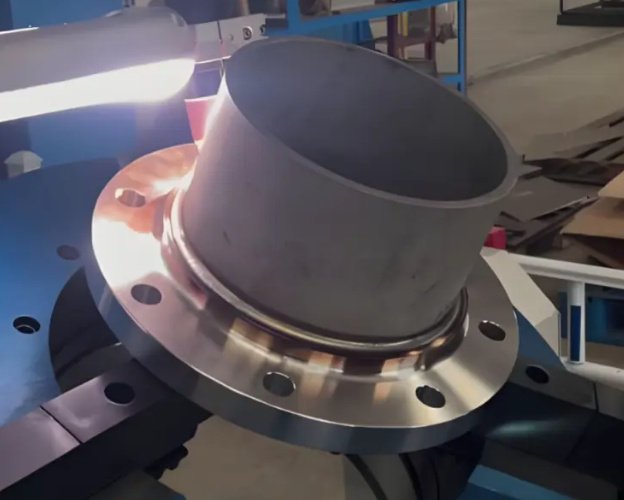
Metal welding is a fabrication process that joins two or more metal parts by applying heat, pressure, filler metal, or a combination of these inputs. It is widely used in sheet metal fabrication, structural steelwork, pressure vessels, automotive frames, machinery, aerospace components, medical equipment, rail systems and industrial enclosures.
The search intent behind “metal welding” is usually practical: users want to understand which welding method fits a material, how strong the joint can be, what defects to avoid, how welding affects machining and finishing, and how to control cost in production. This page explains the major welding processes, design rules, process parameters, quality checks and real manufacturing considerations used in professional metal fabrication.
What Is Metal Welding?
Metal welding creates a permanent joint by forming metallurgical continuity between components. In fusion welding, the base metals are locally melted and solidified. In solid-state welding, joining occurs under pressure and controlled energy without fully melting the base metal. A proper weld is not only a visible bead; it is a controlled heat-affected structure with measurable strength, penetration, geometry and surface quality.
Successful metal welding depends on material compatibility, joint design, heat input, shielding, fixturing and inspection. If any of these variables is ignored, the result may include distortion, cracks, porosity, lack of fusion, undercut, excessive spatter or premature fatigue failure.
Common Metal Welding Processes
Different welding methods solve different engineering problems. The best process is selected according to base metal, thickness, access, production volume, appearance requirements, strength requirements and post-weld operations such as CNC machining, grinding, polishing, coating or heat treatment.
| Process | Typical Materials | Thickness Range | Main Advantages | Common Applications |
|---|---|---|---|---|
| MIG / GMAW | Carbon steel, stainless steel, aluminum | 1.0 mm to heavy plate | Fast deposition, suitable for production welding | Frames, brackets, tanks, enclosures, machinery parts |
| TIG / GTAW | Stainless steel, aluminum, titanium, copper alloys | 0.5 mm to medium thickness | Clean bead, high control, low spatter | Precision assemblies, sanitary tubes, aerospace parts |
| Stick / SMAW | Carbon steel, low-alloy steel, cast iron with proper electrodes | Medium to heavy sections | Portable, robust in field conditions | Construction, repair welding, pipelines, heavy equipment |
| Flux-Cored / FCAW | Carbon steel, structural steel | Medium to heavy sections | High productivity, good outdoor capability | Structural fabrication, shipbuilding, heavy weldments |
| Laser Welding | Stainless steel, carbon steel, aluminum, nickel alloys | Thin to medium sections | Low distortion, narrow heat-affected zone, high speed | Battery trays, electronics housings, precision sheet metal |
| Resistance Spot Welding | Low-carbon steel, coated steel, stainless steel, aluminum with controls | Thin sheet | Very fast, no filler metal required | Automotive panels, cabinets, appliance parts |
MIG Welding
MIG welding, also called gas metal arc welding, uses a continuously fed wire electrode and shielding gas. It is one of the most economical options for steel and aluminum fabrication because it offers high travel speed and good repeatability. For production parts, MIG welding is often combined with jigs, robotic arms, turntables and post-weld grinding.
TIG Welding
TIG welding uses a non-consumable tungsten electrode and separate filler wire when needed. It is slower than MIG welding but provides excellent bead appearance and heat control. TIG is preferred for thin stainless steel, aluminum, titanium, sanitary tubing and visible welds where grinding is undesirable.
Laser Welding
Laser welding concentrates energy into a small area, reducing heat input and distortion. It is increasingly used in precision metal fabrication, battery systems, electronic housings and stainless steel assemblies. The process requires accurate fit-up because the beam is narrow and less tolerant of wide gaps.
When is laser welding better than MIG or TIG welding?
Laser welding is often better when parts are thin, dimensional stability is critical, weld appearance must be clean and high-volume repeatability is required. MIG or TIG may be better for large gaps, thick sections, field repair or lower-volume work where equipment cost must be minimized.
Weldable Metals and Material-Specific Considerations
Not all metals respond to welding in the same way. Thermal conductivity, oxide behavior, carbon content, alloying elements and hardness determine how the weld pool forms and how the heat-affected zone behaves after cooling.
| Metal | Weldability | Key Challenges | Recommended Controls |
|---|---|---|---|
| Carbon Steel | Good | Hydrogen cracking, distortion, spatter | Low-hydrogen consumables, preheat for thicker sections, proper clamping |
| Stainless Steel | Good with correct procedure | Sensitization, heat tint, warping, corrosion loss | Controlled heat input, back purging, pickling or passivation |
| Aluminum | Moderate to good | Oxide layer, porosity, high thermal conductivity | Surface cleaning, AC TIG or proper MIG setup, dry shielding gas |
| Galvanized Steel | Weldable with precautions | Zinc fumes, porosity, coating burn-off | Ventilation, coating removal near weld zone, post-weld corrosion protection |
| Cast Iron | Difficult | Cracking, brittleness, carbon migration | Preheat, nickel filler, slow cooling, short weld beads |
| Copper and Brass | Challenging | High heat conduction, zinc vaporization in brass | High energy input, suitable filler, ventilation, joint cleanliness |
Material selection should be reviewed before welding design is finalized, because the same joint geometry may perform well in mild steel but fail in aluminum or crack in high-carbon steel.
Joint Design and Welding Symbols
Weld strength is strongly influenced by joint design. A well-designed weld joint provides sufficient access for the torch or electrode, controls shrinkage, avoids stress concentration and allows inspection after welding.
Common Weld Joint Types
- Butt joint: Two edges are joined in the same plane. Used for plates, pipes and sheet metal seams.
- Lap joint: One part overlaps another. Common in sheet metal and spot welding.
- T-joint: One member is perpendicular to another. Used in frames, ribs and brackets.
- Corner joint: Two parts meet at an angle, often used in boxes and enclosures.
- Edge joint: Two parallel edges are welded together, typically for light-duty sheet assemblies.
Design Rules for Fabricated Weldments
- Keep welds away from high-stress corners when possible.
- Use intermittent fillet welds where continuous welds are not structurally required.
- Allow access for welding torch angle, filler feeding and cleaning.
- Minimize excessive weld size because over-welding increases cost and distortion.
- Use tabs, slots, locating holes or fixture points for repeatable assembly.
- Specify whether welds must be ground flush, left as-welded, polished or sealed.
- Consider post-weld machining allowance if critical dimensions are required after welding.
How much gap is acceptable before welding?
Acceptable gap depends on the process, material thickness and joint type. For precision laser welding, fit-up may need to be below 0.1 to 0.2 mm. For MIG fillet welding on structural steel, a larger root opening may be tolerated, but excessive gaps increase filler consumption, heat input and distortion risk.
Metal Welding Parameters That Affect Quality
Welding parameters determine penetration, bead profile, microstructure and distortion. In production welding, these parameters are usually documented in a welding procedure specification, commonly called a WPS.
| Parameter | Effect on Weld | Risk if Incorrect |
|---|---|---|
| Current / Amperage | Controls heat generation and penetration | Lack of fusion, burn-through or excessive reinforcement |
| Voltage | Influences arc length and bead width | Spatter, undercut or unstable arc |
| Travel Speed | Determines heat input per unit length | Cold lap, narrow bead, overheating or warping |
| Shielding Gas | Protects molten metal from oxygen and nitrogen | Porosity, oxidation and poor bead appearance |
| Filler Metal | Provides joint metal and alloy compatibility | Cracking, low strength or corrosion mismatch |
| Preheat and Interpass Temperature | Controls cooling rate and hydrogen cracking risk | Cracks, brittle heat-affected zone or reduced toughness |
Heat input is one of the most important welding variables because it directly affects distortion, residual stress, hardness and corrosion performance. For parts requiring tight tolerances, heat input must be controlled together with clamping sequence and weld sequence.
Welding Defects, Causes and Prevention
Welding defects can reduce load capacity, leak tightness, corrosion resistance and fatigue life. Some defects are visible, while others require nondestructive testing or destructive testing to confirm.
| Defect | Typical Cause | Prevention Method |
|---|---|---|
| Porosity | Moisture, oil, paint, poor shielding gas coverage | Clean base metal, dry consumables, correct gas flow |
| Lack of Fusion | Low heat input, poor joint access, incorrect torch angle | Increase energy, improve bevel design, control travel speed |
| Cracking | High restraint, hydrogen, unsuitable filler, rapid cooling | Preheat, low-hydrogen process, proper filler selection |
| Undercut | Excessive current, long arc, fast travel speed | Adjust amperage, shorten arc, refine bead technique |
| Distortion | Uneven shrinkage from heat input | Balanced weld sequence, fixtures, tack welds, lower heat process |
| Excessive Spatter | Incorrect voltage, dirty material, unstable wire feed | Tune parameters, clean surface, maintain welding equipment |
Why do welded metal parts warp after fabrication?
Welded parts warp because molten and heated metal expands during welding and shrinks during cooling. If shrinkage is uneven, the assembly bends, twists or pulls out of tolerance. Warping can be reduced by using balanced weld sequences, strong fixtures, smaller weld sizes, intermittent welds, pre-setting and lower-heat processes such as laser welding.
Quality Control and Inspection Methods
Professional metal welding requires verification before parts are released for machining, coating, assembly or shipment. Inspection level depends on the application. A decorative stainless steel cover may require visual and surface checks, while a pressure component may require radiographic testing, leak testing and procedure qualification.
Common Welding Inspection Methods
- Visual inspection: Checks bead profile, undercut, cracks, spatter, overlap and overall workmanship.
- Dimensional inspection: Verifies flatness, hole position, assembly squareness and post-weld tolerance.
- Dye penetrant testing: Detects surface-breaking cracks on non-porous metals.
- Magnetic particle testing: Finds surface and near-surface defects in ferromagnetic materials.
- Ultrasonic testing: Detects internal discontinuities in thicker welded sections.
- Radiographic testing: Uses X-rays or gamma rays to reveal internal porosity, inclusions and lack of fusion.
- Destructive testing: Includes tensile tests, bend tests, macro-etching and hardness testing.
For critical weldments, inspection criteria should be defined before production using relevant standards such as AWS D1.1 for structural steel, AWS D17.1 for aerospace fusion welding, ASME Section IX for welding qualifications, ISO 5817 for fusion-weld quality levels, or ISO 9606 for welder qualification.
Engineering Problems and Data-Based Results
Real fabrication projects often fail not because welding is impossible, but because welding is treated as a final workshop operation instead of a design-controlled manufacturing process. The following examples show how process changes can improve measurable results.
Case 1: Stainless Steel Enclosure Distortion Reduction
A 304 stainless steel electrical enclosure made from 1.5 mm sheet required visible corner welds and a flat mounting face. Initial TIG welding produced corner pull-in of 1.8 to 2.4 mm after cooling, causing assembly gaps during final installation.
Process changes included shorter weld segments, alternating weld sequence, copper backing bars and reduced interpass temperature. The average corner pull-in decreased from 2.1 mm to 0.7 mm, and post-weld straightening time was reduced by approximately 55%.
Case 2: Aluminum Frame Porosity Control
An aluminum 6061-T6 frame showed scattered porosity during MIG welding. Root cause analysis found inconsistent oxide removal, humidity exposure of filler wire and excessive gas turbulence at the nozzle.
After stainless wire brushing, acetone cleaning, sealed filler storage and optimized shielding gas flow, reject rate dropped from 8.5% to 1.6% over a 500-piece production run. Tensile coupon failures shifted from weld-metal porosity to base-metal yielding, indicating improved weld integrity.
Case 3: Robotic MIG Welding Productivity Improvement
A carbon steel bracket assembly originally used manual MIG welding with variable bead size and frequent grinding. By adding fixture locating pins, part presence sensors and a robotic weld path, arc-on time per assembly decreased from 96 seconds to 58 seconds. Weld length variation was reduced, and grinding labor decreased by about 40% because bead placement became more consistent.
Metal Welding and Downstream Processing
Welding affects later manufacturing steps. A welded assembly may require machining, grinding, polishing, heat treatment, coating, plating, painting or final assembly. Planning these operations early prevents tolerance stack-up and surface defects.
Post-Weld Machining
Welded parts can move after stress relief or rough machining. For precision weldments, it is common to weld first, stress relieve if necessary, rough machine, allow stabilization and then finish machine critical features. Machining datums should be located away from heavy weld shrinkage zones when possible.
Grinding and Surface Finishing
Grinding can improve appearance and remove excess reinforcement, but aggressive grinding may reduce throat size and weaken a fillet weld. Stainless steel parts requiring cosmetic finishing may need progressive abrasive polishing, pickling and passivation to restore corrosion resistance.
Coating and Corrosion Protection
Welds can create coating challenges because spatter, slag, undercut and sharp edges reduce paint adhesion. Before powder coating or painting, welded assemblies should be deburred, cleaned and inspected. Galvanized or zinc-rich repairs may be required when welding damages protective zinc layers.
Downstream processing should be included in the welding plan, especially for parts with tight tolerances, visible surfaces or corrosion-resistance requirements.
Should parts be machined before or after welding?
Rough machining can be done before welding when part location and fit-up are important, but final machining of critical tolerances is often better after welding because heat and shrinkage can move dimensions. For high-precision weldments, a typical route is cut, form, tack, weld, stress relieve if required, rough machine, finish machine and inspect.
Cost Factors in Metal Welding
Welding cost is not only based on bead length. It includes engineering review, fixture design, preparation, consumables, welder skill, inspection, rework risk and finishing. A lower hourly welding cost may still be expensive if it causes distortion, grinding or scrap.
| Cost Driver | Impact | Optimization Strategy |
|---|---|---|
| Material Thickness | Thicker parts require more passes and higher heat input | Use proper bevels, joint efficiency and realistic weld size |
| Weld Length | Long continuous welds increase labor and distortion | Use intermittent welds where design allows |
| Fit-Up Accuracy | Poor fit-up increases filler use and rework | Improve laser cutting, bending accuracy and fixturing |
| Appearance Requirement | Cosmetic welds require higher skill and finishing time | Define acceptable bead finish and grinding zones clearly |
| Inspection Level | NDT and documentation increase project cost | Apply inspection level according to actual risk and standard |
| Production Volume | Low volume favors flexible manual welding; high volume favors automation | Use fixtures, robotic welding or laser welding when volume justifies setup |
How to Choose the Right Metal Welding Method
The right welding method should meet mechanical, dimensional, cosmetic and commercial requirements at the same time. A practical selection workflow includes reviewing the drawing, identifying the base metal, confirming load conditions, checking tolerance needs, selecting the welding process, defining inspection criteria and validating samples before full production.
- Identify base metal grade, thickness and surface condition.
- Define whether the weld is structural, leak-tight, cosmetic or temporary.
- Review joint access, gap tolerance and fixture strategy.
- Compare MIG, TIG, laser, resistance, stick or flux-cored welding based on requirements.
- Select filler metal, shielding gas and preheat requirements.
- Control weld sequence to reduce distortion.
- Inspect first articles before releasing batch production.
For general steel fabrication, MIG welding is often the most efficient choice. For precision stainless steel and aluminum assemblies, TIG or laser welding may provide better appearance and dimensional control. For sheet metal assemblies in high volume, resistance spot welding and robotic laser welding can reduce cycle time. For outdoor structural work, stick welding and flux-cored welding remain practical due to portability and penetration capability.
Key Takeaways
- Metal welding is a controlled joining process, not just the act of melting metal.
- Process selection depends on material, thickness, tolerance, appearance, production volume and inspection requirements.
- Heat input, fit-up, shielding and filler metal strongly affect weld quality.
- Distortion and cracking can often be prevented through design, sequencing and fixturing.
- Welding should be planned together with cutting, bending, machining, finishing and coating.
- Documented procedures and inspection methods improve repeatability in production fabrication.