
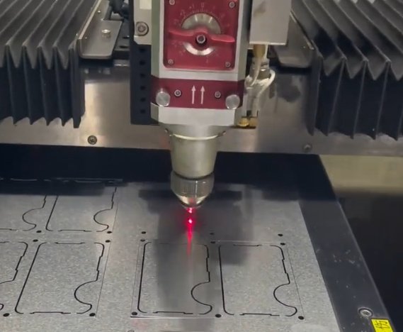
This metal cutting guide explains how common cutting processes work, where each method performs best, and how engineers, buyers and fabricators can specify parts with fewer defects, lower scrap rates and more predictable pricing. It covers sheet metal cutting, plate cutting, tube cutting, bar cutting, precision machining, thermal cutting, abrasive cutting and non-contact cutting methods.
In practical manufacturing, the best metal cutting process is the one that meets tolerance, edge quality, heat input, volume and cost requirements at the same time. A process that is fast for carbon steel plate may be unsuitable for thin stainless parts, aerospace aluminum, hardened tool steel, titanium or cosmetic visible edges.
What Is Metal Cutting?
Metal cutting is the controlled separation or removal of metal using mechanical force, heat, electrical discharge, abrasive particles, high-pressure water, or a combination of these. It is used to produce blanks, profiles, holes, slots, tubes, brackets, machine components, weldments, enclosures and precision parts.
Metal cutting operations generally fall into two categories:
- Profile cutting: creating 2D shapes from sheet, plate or tube, often by laser cutting, plasma cutting, oxy-fuel cutting, waterjet cutting, punching, shearing or sawing.
- Material removal: producing accurate features and surfaces by milling, turning, drilling, reaming, grinding, broaching, EDM or other machining processes.
Key terms used throughout metal cutting include kerf width, heat-affected zone, burr, dross, feed rate, cutting speed, chip load, tool wear, nesting efficiency, cut edge squareness, tolerance stack-up, surface roughness, material hardness and fixture stability.
Metal Cutting Process Comparison
The table below summarizes the most widely used metal cutting methods and the applications where they are typically strongest. Actual performance depends on machine power, tooling, material grade, operator skill, fixturing and inspection requirements.
| Process | Best For | Typical Materials | Typical Thickness Range | Strengths | Limitations |
|---|---|---|---|---|---|
| Fiber laser cutting | Precise sheet and plate profiles | Carbon steel, stainless steel, aluminum, brass, copper | Thin sheet to medium plate; high-power systems can cut thicker plate | High speed, narrow kerf, good repeatability, automation-friendly | Reflective metals require suitable equipment; edge quality changes with thickness |
| CO2 laser cutting | Non-metal and some metal cutting applications | Mild steel, stainless steel, acrylic, wood, plastics | Thin to medium sections | Smooth cuts on many non-metals, mature technology | Lower efficiency than fiber laser for many metals |
| Plasma cutting | Fast cutting of conductive plate | Carbon steel, stainless steel, aluminum | Medium to thick plate | Fast, economical, good for heavy fabrication | Wider kerf, more heat input and more edge taper than laser |
| Oxy-fuel cutting | Very thick carbon steel plate | Low-carbon and mild steel | Thick to very thick plate | Low equipment cost, excellent for heavy steel | Not suitable for stainless or aluminum; large heat-affected zone |
| Waterjet cutting | Heat-sensitive or mixed-material cutting | Steel, stainless, aluminum, titanium, copper, composites, stone, glass | Thin sheet to thick plate | No thermal distortion, versatile material capability | Slower than laser on thin metal; abrasive cost can be significant |
| Band sawing | Bars, tubes, billets and structural profiles | Steel, stainless, aluminum, nickel alloys, titanium | Small stock to large sections | Low cost per cut, good for straight cuts and raw stock preparation | Not for complex profiles; blade selection is critical |
| Shearing | Straight-line sheet cutting | Sheet steel, stainless, aluminum | Thin to moderate sheet thickness | Very fast, low cost, no programming for simple cuts | Limited to straight cuts; can create edge deformation |
| Punching | Sheet metal holes, slots and repetitive features | Steel, stainless, aluminum | Mostly sheet metal | Efficient for repeated holes and forms | Tooling constraints; nibble marks on contours |
| Wire EDM | High-precision hardened metals | Tool steel, carbide, titanium, superalloys, conductive metals | Varies by machine and part geometry | Excellent accuracy, minimal mechanical force, complex profiles | Slower, only conductive materials, higher cost per hour |
| CNC milling and turning | 3D features and tight-tolerance parts | Most machinable metals | Stock-dependent | High dimensional control, threads, pockets, bores and surfaces | More programming and fixturing than simple profile cutting |
Buyer and estimator note: when the cheapest quoted process is not the lowest-cost option
A low cutting price can become expensive if secondary deburring, flattening, rework, masking, machining allowance or weld-fit correction is required. For example, plasma may be economical for a heavy equipment bracket, while laser or waterjet may reduce total cost for thin stainless panels that need clean cosmetic edges and minimal post-processing.
How to Select a Metal Cutting Method
Process selection should begin with the part drawing, not the machine list. Review the base material, thickness, tolerance, edge finish, hole size, bend sequence, welding requirements, coating requirements and expected annual volume.
- Define the material: grade, temper, hardness, coating, mill scale and corrosion resistance all affect cutting performance.
- Confirm thickness and geometry: thin sheet, thick plate, tube, bar and 3D machined parts require different approaches.
- Set tolerance requirements: avoid applying tight tolerances to non-critical features.
- Specify edge requirements: burr-free, oxide-free, weld-ready, paint-ready, cosmetic or machined edge.
- Evaluate heat sensitivity: heat input can cause distortion, hardening, oxide formation or metallurgical changes.
- Calculate total cost: include setup, programming, nesting yield, cutting speed, consumables, scrap, finishing, inspection and logistics.
For many flat metal parts, laser cutting is often preferred for speed and accuracy on thin to medium sheet, while waterjet is preferred where thermal effects are unacceptable and plasma or oxy-fuel are preferred for heavy fabrication where moderate tolerances are acceptable.
Material-Specific Metal Cutting Guidance
Metals do not cut the same way. Thermal conductivity, reflectivity, hardness, work hardening, oxide behavior and alloy chemistry change both cutting speed and finished quality.
Carbon Steel and Mild Steel
Carbon steel is widely cut by fiber laser, plasma, oxy-fuel, saw, shear, punch and machining. Oxygen-assisted laser cutting can produce high cutting speeds and a smooth edge, but it may leave an oxide layer that should be removed before powder coating, painting or critical welding. Nitrogen-assisted laser cutting can produce a cleaner, oxide-free edge at higher assist gas cost.
Stainless Steel
Stainless steel is commonly cut by fiber laser, waterjet, plasma, saw and machining. Nitrogen assist gas is often used in laser cutting to preserve corrosion resistance and avoid oxidation. Because stainless work-hardens, drilling, milling and sawing should use correct feeds, rigid setups and suitable coolant to prevent tool rubbing.
Aluminum
Aluminum has high thermal conductivity and can reflect laser energy, especially in certain conditions. Modern fiber lasers can cut aluminum effectively when equipped for reflective materials. For thick aluminum plate or heat-sensitive parts, waterjet is a strong option. Machining aluminum generally permits high cutting speeds, but chip evacuation and built-up edge control are important.
Copper and Brass
Copper and brass are reflective and thermally conductive. Fiber laser systems designed with back-reflection protection can cut many copper and brass alloys, but process windows are narrower than for mild steel. Waterjet and machining are often selected for thicker copper components or parts requiring no heat-affected zone.
Titanium
Titanium requires careful control because it is reactive at elevated temperatures and has low thermal conductivity. Waterjet, wire EDM and controlled machining are frequently used for aerospace, medical and high-performance titanium parts. If thermal cutting is used, shielding, contamination control and edge qualification may be required.
Tool Steel and Hardened Alloys
Tool steel, hardened steel and nickel-based superalloys can be difficult to machine because of hardness, toughness and heat resistance. Wire EDM, abrasive waterjet, grinding and rigid CNC machining with suitable carbide or ceramic tooling are commonly used. Heat treatment sequence should be considered before choosing the cutting method.
Engineering note: match material condition to the cutting sequence
Cutting before heat treatment may reduce machining cost, but distortion after hardening can require grinding or EDM correction. Cutting after heat treatment may preserve final geometry but increase tool wear or EDM time. The best sequence depends on tolerance, flatness, hardness, batch size and inspection method.
Cutting Parameters That Control Quality
Metal cutting quality is controlled by machine power, speed, feed, tooling, gas, abrasive flow, coolant, workholding and machine condition. A stable process produces consistent kerf width, acceptable edge roughness, controlled burr height and repeatable dimensions.
| Parameter | Applies To | Effect on Cutting | Common Problem if Incorrect |
|---|---|---|---|
| Cutting speed | Laser, plasma, waterjet, saw, milling, turning | Controls heat input, cycle time and edge finish | Dross, taper, rough edge, chatter or tool failure |
| Feed rate | Machining, sawing, drilling | Controls chip thickness and tool load | Rubbing, work hardening, broken tools or poor finish |
| Assist gas type and pressure | Laser cutting | Affects oxidation, kerf evacuation and edge color | Burnt edge, oxide scale, incomplete cut or excessive gas cost |
| Abrasive flow | Waterjet cutting | Controls cut power and edge quality | Slow cutting, taper, striations or high consumable cost |
| Blade pitch and speed | Band sawing | Controls chip formation and blade life | Tooth stripping, crooked cuts or excessive vibration |
| Tool geometry | Milling, turning, drilling, shearing | Controls cutting forces and chip flow | Burrs, heat, poor finish or dimensional drift |
| Workholding rigidity | All processes | Controls vibration and positional accuracy | Chatter, taper, out-of-square edges or part movement |
In machining, chip formation is a diagnostic signal. Blue chips may indicate excessive heat in steel machining, powdery chips can indicate rubbing, and long stringy chips can create safety hazards or surface damage if not controlled.
Kerf, Tolerance, Edge Quality and Heat-Affected Zone
Metal cutting drawings should account for the physical limitations of the selected process. Kerf width, pierce marks, taper, corner radius, edge roughness and heat-affected zone can influence final fit and function.
| Process | Typical Relative Kerf | Typical Edge Quality | Thermal Effect | Common Tolerance Range in General Fabrication |
|---|---|---|---|---|
| Fiber laser | Narrow | Good to excellent on suitable thickness | Low to moderate heat-affected zone | Often around ±0.1 mm to ±0.3 mm depending on thickness and machine capability |
| Plasma | Medium | Good for fabrication, more taper than laser | Moderate heat-affected zone | Often around ±0.5 mm to ±1.5 mm depending on plate thickness and equipment |
| Oxy-fuel | Wide | Suitable for heavy plate | High heat input | Often around ±1.5 mm or more for thick plate applications |
| Waterjet | Medium | Good, with quality depending on speed setting | No heat-affected zone | Often around ±0.1 mm to ±0.5 mm depending on thickness and cut quality |
| Wire EDM | Very narrow | Excellent | Very localized thermal effect | Can hold very tight tolerances in precision applications |
| CNC machining | Tool-dependent | Excellent with proper finishing passes | Controlled by toolpath and coolant | Can hold tight tolerances when machine, tooling and inspection support it |
Published tolerances should be verified with the supplier because they vary by material thickness, part size, feature location, machine calibration, thermal expansion and inspection standard. Do not assume that a cut edge is equivalent to a machined datum unless the drawing requires machining.
Machining and Secondary Operations After Cutting
Many metal parts need more than one cutting operation. A laser-cut blank may be bent, tapped, countersunk, machined, deburred, welded and coated. A saw-cut billet may be milled and drilled. A waterjet-cut titanium plate may need finish machining on critical edges.
Common secondary operations include:
- Deburring: removal of sharp edges, burrs and dross by tumbling, brushing, grinding, sanding or manual finishing.
- Drilling and tapping: producing threaded holes after cutting when laser-cut or punched holes are not suitable.
- Countersinking and counterboring: preparing fastener seats for assemblies and enclosures.
- Face milling: improving flatness, parallelism or surface finish on critical faces.
- Grinding: achieving tight thickness control, flatness or fine surface finish.
- Chamfering and radius finishing: improving safety, coating adhesion and fatigue performance.
- Heat treatment: changing hardness, strength or stress condition after rough cutting.
For assemblies, cutting accuracy must be considered together with bending, welding and finishing distortion. A flat blank that meets tolerance can still create an out-of-tolerance assembly if bend deductions, weld shrinkage or coating buildup are not included in the process plan.
Real engineering example: reducing rework in stainless sheet parts
A stainless control-panel bracket was originally plasma cut from 3 mm sheet and required manual grinding before visible installation. Switching to nitrogen-assisted fiber laser cutting increased cutting cost per sheet but reduced deburring time by more than 60% and improved hole consistency for fastener alignment. The total part cost decreased because finishing labor and rejected cosmetic edges were reduced.
Common Metal Cutting Defects and How to Prevent Them
Cutting defects are usually caused by poor parameter selection, worn consumables, incorrect material support, thermal distortion, programming errors, improper tooling or insufficient inspection. The following table can help identify root causes.
| Defect | Likely Causes | Prevention |
|---|---|---|
| Burrs | Dull tooling, incorrect feed, poor die clearance, inadequate gas pressure, wrong speed | Use correct tooling, optimize speed and feed, maintain consumables, verify material support |
| Dross or slag | Incorrect laser or plasma settings, low gas pressure, slow speed, contaminated surface | Adjust speed and power, clean material, check nozzle condition, use correct assist gas |
| Edge taper | Plasma arc behavior, waterjet lag, incorrect standoff, excessive speed | Use quality settings, adjust standoff, slow down for critical edges, consider secondary machining |
| Heat distortion | High heat input, thin material, poor nesting sequence, residual stress | Use lower heat process, balanced toolpath, tabs or fixtures, stress-relieved material when needed |
| Chatter | Low rigidity, excessive tool overhang, wrong cutting parameters, unstable workholding | Improve clamping, reduce overhang, change feeds and speeds, use appropriate tool geometry |
| Work hardening | Rubbing instead of cutting, low feed, dull tools, poor coolant | Maintain chip load, use sharp tools, apply suitable coolant, avoid dwell in stainless and nickel alloys |
| Poor hole roundness | Piercing limitations, small hole-to-thickness ratio, tool deflection, thermal expansion | Drill or ream critical holes, increase hole diameter, use lead-ins, specify machined holes where necessary |
Inspection should match the risk of the part. Calipers may be adequate for simple brackets, while coordinate measuring machines, optical comparators, surface roughness gauges, hardness testing and first article inspection may be required for precision or regulated components.
Cost Drivers in Metal Cutting
Metal cutting cost is not determined only by machine time. A realistic quote includes material utilization, setup, programming, piercing time, tool wear, consumables, operator time, inspection, scrap risk and secondary operations.
- Material yield: nesting efficiency can significantly affect sheet and plate cost, especially for stainless, aluminum, copper and titanium.
- Part complexity: many small holes, tight internal corners and long cut paths increase cycle time.
- Thickness: thicker material generally cuts slower and requires more power, abrasive, gas or tooling load.
- Tolerance: tight tolerances may require slower cutting, finish machining or additional inspection.
- Batch size: small batches carry more setup cost per part; larger batches benefit from nesting and repeatability.
- Edge requirements: burr-free, oxide-free or cosmetic edges may require premium process settings or secondary finishing.
- Material traceability: certified material, heat numbers and documentation add administrative and quality-control requirements.
As a rule, over-specifying tolerances is one of the most common causes of unnecessary cutting cost. Features that only require clearance should not be specified like bearing fits or locating datums.
Procurement checklist for quoting metal cut parts
- Provide 2D drawings and 3D files when available, such as DXF, DWG, STEP or IGES.
- Specify material grade, thickness, temper, finish and certification needs.
- Identify critical dimensions, datum features and inspection requirements.
- Clarify whether cut edges must be deburred, oxide-free, weld-ready or cosmetic.
- State annual volume, release quantity, packaging requirements and revision control process.
- Confirm whether substitutions are allowed for material grade, thickness or process.
Design Tips for Better Metal Cutting Results
Good design for manufacturability improves lead time, consistency and cost. The following guidelines are useful for laser cutting, plasma cutting, waterjet cutting, punching and machining, but exact limits should be confirmed with the selected supplier.
- Avoid internal corner radii smaller than the process can produce; use radius values that match cutting or machining capability.
- Keep holes larger than the minimum recommended diameter for the material thickness and process.
- Allow enough spacing between holes, edges and bends to reduce distortion and cracking.
- Use common material thicknesses to reduce procurement lead time.
- Separate critical and non-critical tolerances on the drawing.
- Mark cosmetic surfaces and grain direction requirements when appearance matters.
- Design tabs, micro-joints or part skeleton support when small parts may tip during cutting.
- Specify whether burr direction matters for assembly, sealing or safety.
- Include coating buildup allowance for plated, anodized, painted or powder-coated parts.
For precision assemblies, create a tolerance strategy before releasing the cutting drawing. Datum structure, hole position, slot clearance, bend location and weld sequence should work together instead of being treated as isolated features.
Safety, Sustainability and Process Control
Metal cutting requires control of heat, fumes, sharp edges, noise, dust, high-pressure systems, rotating tools and electrical hazards. Effective shops use machine guarding, ventilation, fire prevention, personal protective equipment, lockout procedures and documented maintenance schedules.
Sustainability in metal cutting is improved by better nesting yield, recyclable scrap segregation, efficient assist gas use, coolant management, longer tool life and reduced rework. In high-volume production, even a small improvement in material utilization can have a measurable impact because sheet, plate and bar stock often represent a large share of total part cost.
Process control should include revision management, first-off inspection, periodic dimensional checks, consumable tracking, machine calibration and clear acceptance criteria. For critical industries such as aerospace, medical, energy and transportation, additional requirements may include full material traceability, process qualification, documented inspection records and compliance with customer-specific standards.
Quick Selection Summary
| Requirement | Likely Best Starting Point | Reason |
|---|---|---|
| Thin sheet with high accuracy | Fiber laser cutting | Fast, repeatable and narrow kerf |
| Very thick carbon steel plate | Oxy-fuel or plasma cutting | Economical for heavy fabrication |
| No heat-affected zone | Waterjet cutting | Cold cutting avoids thermal distortion and metallurgical changes |
| Hardened precision profile | Wire EDM | High accuracy with low mechanical force |
| Round bar, tube or billet cutoff | Band sawing | Efficient straight cutting of stock material |
| Threads, bores, pockets and tight datums | CNC machining | Controlled 3D material removal and precision features |
| Simple straight sheet cuts | Shearing | Very fast and economical for rectangular blanks |
A reliable metal cutting decision balances process capability with the real function of the part. Start with the drawing requirements, understand the material behavior, confirm tolerance and edge expectations, and evaluate total manufacturing cost rather than cutting price alone.