
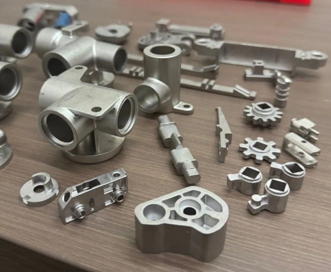
Metal forming is a manufacturing method that changes the shape of metal through plastic deformation rather than material removal. It is used to produce brackets, housings, automotive panels, structural profiles, fasteners, pressure vessels, aircraft fittings, heat exchangers, appliance parts and many other components where strength, repeatability and material efficiency matter.
Unlike machining, which cuts away material, metal forming redistributes material using dies, punches, rollers, presses, hammers or hydraulic pressure. The result can be high productivity, improved grain flow, low scrap rates and strong mechanical performance when the process is matched correctly to the part geometry, material grade, production volume and tolerance requirements.
What Is Metal Forming?
Metal forming is the controlled deformation of sheet, plate, bar, tube, wire or billet into a desired shape. The workpiece is stressed beyond its yield strength but below its fracture limit. Common forming forces include compression, tension, bending, shear and combinations of these loads.
The process may be performed at room temperature, warm temperature or high temperature. Cold forming generally provides better surface finish and dimensional control, while hot forming lowers required forming force and improves ductility for difficult materials or large cross sections.
| Category | Typical feedstock | Common processes | Typical applications |
|---|---|---|---|
| Sheet metal forming | Sheet, strip, coil, plate | Stamping, bending, deep drawing, roll forming, hydroforming | Enclosures, brackets, panels, cans, chassis parts |
| Bulk metal forming | Billet, bar, rod, wire, tube | Forging, extrusion, rolling, heading, swaging | Gears, shafts, fasteners, fittings, structural profiles |
| Tube forming | Round, square or rectangular tube | Tube bending, end forming, tube hydroforming, flaring | Frames, exhaust systems, fluid lines, medical components |
Main Metal Forming Processes
Sheet Metal Stamping
Stamping uses a press and die set to cut, blank, pierce, emboss, draw or form sheet metal. It is widely used for automotive, electronics, appliances and industrial hardware. Progressive dies can combine several operations in one tool, making stamping suitable for high-volume production.
Stamping is often selected when part volumes justify tooling investment and when features such as holes, flanges, ribs, tabs and shallow drawn shapes must be produced with consistent repeatability.
Bending and Press Brake Forming
Bending uses a punch and die, folding beam, roll set or press brake to create angles in sheet or plate. Critical parameters include inside bend radius, material thickness, bend allowance, K-factor, grain direction and springback compensation.
Air bending is flexible and common for lower to medium volumes. Bottoming and coining can improve angle repeatability but require higher tonnage and more tooling control.
Deep Drawing
Deep drawing pulls sheet metal into a die cavity to create cups, cans, shells and enclosures. A part is generally considered deep drawn when its depth is significant relative to its diameter or opening width. The process requires careful blank size calculation, blank holder force, draw bead design and lubrication.
Deep drawing is sensitive to thinning, wrinkling, earing, tearing and anisotropy. Materials with good elongation and favorable r-values are preferred for severe draws.
Roll Forming
Roll forming passes coil strip through sequential roller stations to gradually form a constant cross-section profile. It is efficient for long parts such as channels, rails, frames, roof panels, drawer slides and structural members.
The process supports inline punching, embossing, cut-to-length operations and high production speed. It is most economical for profiles with consistent geometry over long lengths.
Forging
Forging compresses heated or cold metal between dies or under hammers to produce strong components with directional grain flow. Open-die forging is used for large or simple shapes, while closed-die forging creates near-net-shape parts such as crankshafts, connecting rods, gears, valves and aerospace fittings.
Forged parts often outperform cast or machined-from-bar components in fatigue-critical applications because the metal flow can be aligned with service loads.
Extrusion
Extrusion forces metal through a die to create long parts with a continuous cross section. Aluminum extrusion is common for frames, heat sinks, rails and architectural profiles. Steel, copper, brass, magnesium and titanium alloys can also be extruded under suitable conditions.
Extrusion is strong for profiles that would be inefficient to machine from solid stock, especially when weight reduction and integrated features are important.
Hydroforming
Hydroforming uses high-pressure fluid to shape sheet or tube material against a die. Tube hydroforming is common in automotive structures, bicycle frames and fluid-handling components. Sheet hydroforming can create complex, smooth panels with reduced tooling contact marks.
Spinning and Incremental Forming
Metal spinning rotates a blank while tools form it over a mandrel, making cones, hemispheres, reflectors, cookware and pressure vessel ends. Incremental sheet forming uses CNC-controlled tools to gradually deform a sheet without a dedicated full die, making it attractive for prototypes, aerospace panels and low-volume custom parts.
Cold Forming, Warm Forming and Hot Forming
| Method | Forming temperature | Advantages | Limitations |
|---|---|---|---|
| Cold forming | Below recrystallization temperature | Good surface finish, tight tolerances, work hardening, high productivity | Higher forming load, risk of cracking in low-ductility materials |
| Warm forming | Between cold and hot working ranges | Improved formability, lower press load, better accuracy than hot forming | Requires temperature control and suitable lubricants |
| Hot forming | Above recrystallization temperature | High ductility, lower forming force, suitable for large sections | Scale, oxidation, wider tolerances, possible post-processing |
Cold forming is common for sheet metal stamping, press brake bending, cold heading and roll forming. Hot forming is commonly used in forging, hot stamping of boron steel, hot extrusion and heavy plate forming. Warm forming can be valuable for aluminum, magnesium, titanium and stainless steel when room-temperature ductility is not sufficient.
Materials Used in Metal Forming
Material selection determines formability, tooling wear, press tonnage, part strength, corrosion performance and cost. Engineers often evaluate yield strength, tensile strength, elongation, strain hardening exponent, plastic strain ratio, hardness, thickness tolerance and surface condition before committing to tooling.
| Material group | Typical forming behavior | Common formed parts |
|---|---|---|
| Low-carbon steel | Excellent general formability and weldability; widely used for stamping and bending | Brackets, covers, frames, automotive panels |
| High-strength low-alloy steel | Higher strength but more springback and higher forming load | Structural automotive parts, reinforcements, brackets |
| Stainless steel | Good corrosion resistance; work hardens rapidly; requires robust tooling and lubrication | Appliance parts, medical trays, food equipment, housings |
| Aluminum alloys | Lightweight and corrosion resistant; springback and galling must be managed | Aircraft panels, heat sinks, enclosures, vehicle components |
| Copper and brass | High ductility and conductivity; suitable for electrical and thermal components | Connectors, terminals, heat exchanger parts, decorative hardware |
| Titanium alloys | High strength-to-weight ratio; difficult formability at room temperature; often warm or hot formed | Aerospace brackets, medical parts, high-performance structures |
Standards often used to characterize forming materials include ASTM E8 or ISO 6892 for tensile testing, ASTM E517 for plastic strain ratio, ASTM E646 for strain hardening exponent and ISO 12004 for forming limit curve evaluation.
Design Guidelines for Metal Formed Parts
Good design for metal forming reduces cracking, wrinkling, tool wear, secondary operations and dimensional variation. Early design review is especially important when the part includes sharp bends, deep pockets, tight flange heights, pierced holes near bends or high-strength alloys.
- Use generous inside bend radii when material ductility is limited or grain direction is unfavorable.
- Keep holes, slots and notches away from bend lines to prevent distortion and tearing.
- Avoid abrupt section changes in drawn or stamped parts; use transitions, radii and beads where possible.
- Specify tolerances based on process capability, not only ideal CAD geometry.
- Consider springback for high-strength steel, stainless steel, aluminum and titanium.
- Match surface finish requirements to real tooling contact conditions and post-processing needs.
- Account for burr direction, grain direction, coating, temper and blank orientation.
For sheet metal bending, an inside bend radius of approximately 1 material thickness is often a practical starting point for mild steel, though actual values depend on alloy, temper and bend method. For brittle or high-strength grades, larger radii may be required. For precision stamped components, bend radius, material thickness tolerance and tool wear should be reviewed together.
Engineering design checklist for manufacturable formed parts
- Confirm material grade, temper, coating and thickness tolerance before finalizing tooling.
- Review the minimum bend radius relative to tensile elongation and rolling direction.
- Check whether holes near bends will elongate or require post-form piercing.
- Use finite element forming simulation for deep draws, complex stampings or high-strength materials.
- Define acceptable burr height, edge condition, cosmetic class and inspection datum scheme.
- Plan for springback compensation in the die, press brake program or forming sequence.
- Confirm whether secondary operations such as trimming, deburring, heat treatment, welding or coating are required.
Typical Tolerances, Surface Quality and Production Results
Achievable tolerances vary by material, thickness, tool condition, part size, press accuracy and measurement method. The figures below are practical industrial ranges, not universal guarantees. Critical dimensions should be validated through prototype trials, capability studies and agreed inspection standards.
| Process | Typical production strength | Common tolerance considerations |
|---|---|---|
| Progressive die stamping | High-volume, low unit cost after tooling | Feature tolerances may reach tight ranges on controlled dimensions; burr and strip progression affect results |
| Press brake bending | Flexible for low to medium volume | Angle variation depends on material thickness, tooling, back gauge accuracy and operator setup |
| Deep drawing | Efficient for cups, shells and seamless enclosures | Wall thinning, earing and flange flatness require process control |
| Roll forming | Excellent for long profiles and coil-fed production | Straightness, twist, camber and cut length are key controls |
| Forging | High strength and fatigue resistance | Draft angle, flash line, die shift and machining allowance affect final dimensions |
Process capability is usually confirmed with first article inspection, statistical process control and capability indices such as Cp and Cpk for critical dimensions. For safety-critical parts, dimensional inspection may be combined with hardness testing, tensile testing, microstructure review, coating inspection or non-destructive testing.
Common Metal Forming Defects and Root Causes
Most forming defects are related to an imbalance between material formability, part geometry, lubrication, tooling and forming force. Identifying the true mechanism is important because the same visible defect can have several different causes.
| Defect | Typical cause | Possible corrective actions |
|---|---|---|
| Cracking or tearing | Excessive strain, small radius, poor material ductility, unfavorable grain direction | Increase radius, change blank shape, improve lubrication, select higher-elongation material |
| Wrinkling | Compressive instability, low blank holder force, excess material flow | Increase blank holder force, add draw beads, revise blank size or flange geometry |
| Springback | Elastic recovery after unloading, especially in high-strength alloys | Overbend, coin, restrike, modify tooling, use simulation compensation |
| Thinning | Localized tensile strain during drawing or stretching | Optimize lubrication, draw ratio, die radius and blank holder force |
| Galling | Adhesive wear between workpiece and tool surface | Use suitable coatings, polish tooling, improve lubrication, reduce contact stress |
| Burrs | Excessive punch-die clearance, dull tools, improper cutting condition | Sharpen tooling, adjust clearance, control material thickness variation |
Springback is one of the most common engineering challenges in bending, stamping and roll forming. High-strength steel and aluminum can show significant elastic recovery, so the final tool shape may intentionally differ from the nominal part shape.
Example engineering issue: reducing cracks in a stainless steel drawn shell
A stainless steel shell with a deep corner radius may crack near the punch radius if material flow is restricted and local strain exceeds the forming limit. In a typical corrective study, engineers may increase the punch radius, polish the die entry, change lubricant viscosity, adjust blank holder force and revise the blank outline.
In practical production, this type of change can reduce scrap from double-digit percentages to low single digits when the root cause is localized tensile strain rather than material contamination or press misalignment. The exact result depends on alloy, thickness, tool condition and draw depth.
Forming Simulation, Testing and Quality Control
Modern metal forming projects often use finite element analysis to predict strain distribution, thinning, wrinkling, springback and forming load before tooling is cut. Simulation is especially valuable for deep drawing, automotive panels, hot stamping, hydroforming and high-strength sheet forming.
Forming limit diagrams help engineers estimate whether sheet metal will safely form or fail by comparing major and minor strains against a material forming limit curve. Strain measurement may be performed using grid analysis, optical measurement systems or digital image correlation.
Quality control for formed parts may include:
- First article inspection and production part approval processes.
- Coordinate measuring machine inspection, gauges, laser scanning or optical measurement.
- Thickness checks in drawn or stretched regions.
- Hardness testing and tensile testing for formed or heat-treated parts.
- Surface inspection for scratches, galling, orange peel, tool marks and coating damage.
- Statistical process control for critical dimensions and high-volume production.
Cost Drivers in Metal Forming
Metal forming cost is not determined by part weight alone. Tooling complexity, press time, material utilization, scrap rate, tolerance requirements, secondary operations and inspection requirements can have a larger effect on total cost than raw material price.
| Cost factor | Why it matters |
|---|---|
| Tooling and die complexity | Progressive dies, draw dies, forging dies and hydroforming tools require engineering, machining, tryout and maintenance |
| Material utilization | Nesting efficiency, blank shape and trim scrap directly affect cost per part |
| Production volume | High tooling cost may be justified for large volumes but not for prototypes or short runs |
| Press tonnage and cycle time | Higher force requirements and slower cycles increase machine cost |
| Secondary operations | Deburring, machining, welding, heat treatment, coating and assembly add cost and lead time |
| Inspection requirements | Critical parts may require documented capability, traceability and special testing |
Total landed part cost should include tooling amortization, material yield, logistics, quality risk, packaging, rework exposure and the cost of engineering changes. A design that is slightly simpler to form may reduce not only unit price but also launch risk.
Buyer and sourcing considerations for formed metal components
- Ask whether the supplier has experience with the specific process, alloy and annual volume.
- Review tooling ownership, maintenance responsibility, expected die life and replacement insert cost.
- Confirm whether the supplier can support prototyping, pilot runs, PPAP or equivalent quality documentation.
- Check in-house capabilities for forming, trimming, deburring, welding, coating and inspection.
- Clarify material traceability, lot control and change management before production release.
- Evaluate packaging requirements for cosmetic surfaces and thin formed edges.
How to Choose the Right Metal Forming Process
The best forming process depends on geometry, material behavior, annual volume, tolerance level, mechanical performance and investment constraints. For example, a simple bent bracket may be best made with laser cutting and press brake forming at low volume, but the same part may move to progressive die stamping when annual volume increases.
| Requirement | Processes often considered |
|---|---|
| Low-volume sheet metal parts | Laser cutting, turret punching, press brake bending, incremental forming |
| High-volume brackets or clips | Progressive die stamping, four-slide forming, automated bending |
| Seamless cups or housings | Deep drawing, ironing, hydroforming, spinning |
| Long constant profiles | Roll forming, extrusion |
| High-strength load-bearing parts | Closed-die forging, hot forming, cold forging, extrusion with heat treatment |
| Lightweight tubular structures | Tube bending, tube hydroforming, end forming |
Process choice should be made before final design freeze. Changing a bend radius, flange height, hole location or alloy temper early may avoid expensive tooling modifications later.
Practical process selection example
A 2 mm thick steel mounting bracket needed 200 prototypes and later 150,000 parts per year. For prototypes, laser cutting plus press brake bending minimized upfront cost and allowed quick design changes. For production, progressive die stamping reduced handling, improved repeatability and lowered unit cost after tooling approval.
This staged approach is common: flexible fabrication validates the design first, then dedicated forming tooling supports production economics.
Why Metal Forming Remains Important in Modern Manufacturing
Metal forming remains essential because it can produce strong, lightweight and repeatable parts with efficient material use. The process supports both simple brackets and highly engineered components used in automotive, aerospace, electronics, construction, energy, medical and consumer products.
Successful projects combine material knowledge, tooling design, press capability, simulation, lubrication, inspection and design-for-manufacturing discipline. When these factors are aligned, metal forming can deliver reliable mechanical performance, high production throughput and competitive cost per part.