
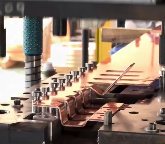
Metal stamping is a high-volume manufacturing process that converts flat metal coil or sheet into precise components through cutting, forming, bending, drawing, embossing, coining and other die-based operations. It is widely used for brackets, terminals, clips, shields, washers, electronic contacts, automotive parts, appliance components, medical device hardware and industrial assemblies.
For buyers, engineers and product teams, the main search intent behind metal stamping is usually practical: how to choose the right stamping method, what tolerances are realistic, how tooling cost affects unit price, which materials work best, and how to reduce risk before production launch. This guide explains those points from a manufacturing and sourcing perspective.
What Is Metal Stamping?
Metal stamping uses a press and a dedicated die set to shape metal by applying controlled force. The die contains punches, cutting edges, forming stations, pads, strippers, pilots and other tooling features that guide the material and create the finished geometry. Depending on part complexity, the process may involve a single operation or many sequential operations in one automated line.
The value of stamping is its ability to produce repeatable parts at speed. Once tooling is validated, stamping can deliver precision, consistent geometry and low unit cost for medium- to high-volume production. This makes it different from laser cutting or CNC machining, which can be more flexible for prototypes but are often slower or more expensive at scale.
Common Metal Stamping Processes
Different stamping methods are selected according to part geometry, volume, tolerance, material thickness, forming depth and annual demand.
| Process | Best For | Typical Advantages |
|---|---|---|
| Progressive die stamping | High-volume parts with multiple features | Fast cycle times, stable repeatability, low unit cost after tooling |
| Transfer die stamping | Larger or deeper formed parts | Good for parts that must be separated from strip before later forming |
| Compound die stamping | Flat parts requiring blanking and piercing in one stroke | Good dimensional accuracy and high productivity |
| Deep drawing | Cups, shells, housings and seamless hollow forms | Reduces welding, improves structural continuity |
| Fourslide or multislide stamping | Small clips, springs, wire forms and complex bends | Efficient forming from multiple directions |
| Short-run stamping | Lower volumes, bridge production or design validation | Lower initial tooling investment, faster iteration |
In many commercial applications, progressive die stamping is preferred because each press stroke advances the strip through multiple stations. Operations such as pilot hole creation, piercing, lancing, forming, tapping, blanking and part cutoff can be integrated into one die.
Metal Stamping Materials
Material selection affects formability, springback, corrosion resistance, conductivity, tensile strength, tool wear, surface finish and cost. The same part geometry may behave very differently when changed from low-carbon steel to stainless steel or from brass to beryllium copper.
| Material | Common Uses | Engineering Notes |
|---|---|---|
| Low-carbon steel | Brackets, washers, frames, general hardware | Good formability and economical pricing; often plated or coated for corrosion resistance |
| Stainless steel 301, 304, 316 | Clips, medical components, food equipment, corrosion-resistant parts | Higher strength and work hardening; requires careful die clearance and lubrication |
| Spring steel | Retainers, clips, spring contacts, locking features | Requires attention to heat treatment, grain direction and fatigue life |
| Aluminum 5052, 6061, 3003 | Lightweight brackets, shields, covers, heat transfer parts | Low density and good corrosion resistance; may gall without proper tooling and lubrication |
| Copper and brass | Electrical terminals, connectors, contacts, shielding | Excellent conductivity; material price volatility can strongly affect cost |
| Phosphor bronze and beryllium copper | High-performance springs, battery contacts, precision electrical parts | Good fatigue resistance and conductivity; often used where reliability is critical |
Material thickness in stamping can range from thin foils below 0.1 mm to heavy-gauge stock above 6 mm, depending on press capacity, die design and part geometry. For most precision stamped components, common thicknesses fall between 0.2 mm and 3.0 mm.
Key Design Considerations for Stamped Parts
Design for manufacturability is one of the biggest factors in stamping success. A part that looks simple in CAD may be difficult to stamp if it has tight inside radii, holes too close to bends, narrow tabs, unbalanced forms or tolerance requirements that conflict with material behavior.
- Keep minimum hole diameter close to or greater than material thickness when possible.
- Avoid placing holes too near a bend line; distortion can occur during forming.
- Use bend radii that match material ductility and thickness.
- Consider grain direction for spring parts, bends and fatigue-loaded features.
- Define datum structures clearly so inspection matches functional requirements.
- Avoid unnecessary cosmetic specifications on non-visible surfaces.
- Review burr direction when the part interfaces with seals, wires, mating surfaces or human handling.
Good stamped-part design improves material utilization, reduces die complexity, shortens tryout time and improves production stability. Small changes such as increasing an inside radius, widening a bridge, changing a notch shape or relaxing a non-critical tolerance can reduce scrap and tool wear.
Engineering note: common DFM issues found during stamping review
Engineers often find that early drawings over-specify tolerances on non-functional dimensions while under-specifying critical features such as burr direction, flatness, datum references, plating thickness or edge condition. A practical DFM review usually checks blank layout, carrier design, strip progression, forming sequence, pilot strategy, press tonnage, feed accuracy and inspection method before tooling is built.
Typical Metal Stamping Tolerances
Stamping tolerances depend on material thickness, part size, press accuracy, die construction, feature type, feed control, material mechanical properties and measurement method. Very tight tolerances are possible, but they must be justified by function because they can increase tooling cost, maintenance frequency and inspection effort.
| Feature Type | Typical Commercial Range | Notes |
|---|---|---|
| Blanked outside profile | ±0.05 mm to ±0.20 mm | Depends on part size, material thickness and die wear |
| Pierced hole diameter | ±0.03 mm to ±0.10 mm | Precision tooling can hold tighter values for stable materials |
| Hole-to-hole location | ±0.05 mm to ±0.15 mm | Piloting and strip stability are important |
| Form height | ±0.10 mm to ±0.30 mm | Influenced by material temper, springback and forming sequence |
| Bend angle | ±1° to ±3° | Can be improved with over-bending, calibration or secondary operations |
| Flatness | Application-dependent | Often affected by residual stress, blanking pattern and forming balance |
For formed parts, springback is a major control variable. High-strength steel, stainless steel and spring temper alloys tend to recover elastically after forming, which can change bend angles and dimensions. Compensation may include over-forming, restrike stations, coining, heat treatment, or material temper control.
Tooling, Dies and Press Equipment
Tooling is the core asset in metal stamping. A die may include die shoes, guide posts, punches, die inserts, retainers, strippers, pressure pads, cams, lifters, sensors, nitrogen springs and carbide or tool-steel wear components. The design must balance durability, maintainability, material flow and part accuracy.
Press selection depends on tonnage, shut height, bed size, stroke length, speed, feed system and required energy. Mechanical presses are common for high-speed blanking and forming. Hydraulic presses provide more controllable force through the stroke and are often used for drawing or forming operations requiring dwell.
| Tooling Factor | Impact on Production | Risk if Ignored |
|---|---|---|
| Die clearance | Controls burr, rollover, burnish and fracture zone | Excessive burrs, short punch life, poor edge quality |
| Punch material and coating | Improves wear resistance and reduces galling | Frequent tool sharpening and unstable dimensions |
| Strip layout | Affects scrap rate and feed stability | High material cost and misfeeds |
| Piloting strategy | Maintains feature location accuracy | Hole misalignment and inconsistent part geometry |
| Sensor integration | Detects misfeeds, slug pulls and part ejection failures | Die crashes, downtime and scrap spikes |
Planned die maintenance is essential for stable stamping quality. Maintenance activities may include sharpening punches, polishing forming surfaces, replacing springs, checking guide wear, measuring punch-to-die clearance, cleaning slug paths and verifying sensor function.
Secondary Operations and Finishing
Many stamped components require secondary processing after the press operation. These processes improve function, corrosion resistance, assembly readiness or cosmetic appearance.
- Deburring, tumbling, vibratory finishing or brushing
- Tapping, thread forming, staking or riveting
- Welding, spot welding, brazing or mechanical assembly
- Heat treatment, stress relief, hardening or tempering
- Electroplating, tin plating, nickel plating, zinc plating or passivation
- Anodizing, powder coating, e-coating, painting or black oxide
- Cleaning, ultrasonic washing, degreasing and packaging for contamination control
Finishing requirements should be defined early because plating thickness, masking, hydrogen embrittlement relief, surface roughness, conductivity and corrosion testing can affect both design and cost. For electrical terminals, plating zones may be more important than overall coating coverage. For stainless parts, passivation may be used to improve corrosion performance without changing dimensions significantly.
Quality Control for Metal Stamped Parts
Quality planning for stamping usually includes drawing review, material certification, first article inspection, in-process checks, final inspection and lot traceability. Automotive, medical, aerospace and electronics applications may require PPAP, APQP, FAI, control plans, capability studies or special process validation.
Important inspection methods include calipers, micrometers, pin gauges, optical comparators, vision systems, CMM inspection, contour measurement, hardness testing, coating thickness measurement and functional gauges. For high-volume stamping, custom go/no-go gauges are often more efficient than measuring every feature manually.
Process capability is commonly tracked through Cpk values on critical dimensions. A Cpk of 1.33 is often used as a general production benchmark, while more critical applications may require 1.67 or higher. However, capability targets should match actual part function, measurement uncertainty and production volume.
Buyer note: what to check in a stamping quality plan
A practical quality plan should identify critical-to-function dimensions, sampling frequency, inspection equipment, material lot traceability, plating or heat-treatment controls, packaging requirements and nonconforming material procedures. For complex parts, ask whether capability data is based on a short trial run or sustained production lots, because early samples may not fully represent tool wear, coil variation or operator changeover conditions.
Cost Drivers in Metal Stamping
Metal stamping cost is usually divided into tooling cost, material cost, press time, labor, secondary operations, quality requirements, packaging and logistics. Unit cost normally decreases as production volume increases, but only when the part is designed for efficient strip layout and stable production.
| Cost Driver | Why It Matters | Optimization Approach |
|---|---|---|
| Tooling complexity | More stations, cams, tight forms and sensors increase die cost | Simplify features, combine operations only where justified |
| Material grade and thickness | Material can dominate unit price, especially copper alloys and stainless steel | Validate the lowest suitable grade and temper |
| Scrap rate | Poor strip layout increases material waste | Improve nesting, carrier width and feed pitch |
| Press speed | Higher strokes per minute reduce machine time per part | Stabilize feeding, ejection and lubrication |
| Secondary operations | Deburring, plating, tapping and assembly add cost and lead time | Design features that can be produced in-die when practical |
| Inspection burden | Overly tight tolerances increase measurement time | Apply tight tolerances only to functional dimensions |
For sourcing decisions, total landed cost is more useful than piece price alone. A lower unit price can become expensive if it leads to high scrap, unstable delivery, rework, sorting, premium freight or engineering changes after tooling release.
Procurement note: questions that reveal real stamping cost
Useful sourcing questions include: What is the expected strip utilization? Which features drive die complexity? What press speed is assumed in the quote? Are deburring, plating, packaging and inspection included? What material price index is used for copper, stainless steel or aluminum? What maintenance interval is expected before sharpening or insert replacement? These answers help compare suppliers beyond headline piece price.
Engineering Examples and Measurable Results
The following examples show how small engineering decisions can affect stamped-part performance, quality and cost. Results vary by material, geometry and production conditions, but the patterns are common in manufacturing reviews.
| Engineering Issue | Change Applied | Measured or Typical Result |
|---|---|---|
| Excessive burr on 0.8 mm stainless steel clip | Adjusted die clearance, added punch coating and controlled sharpening interval | Burr height reduced from about 0.09 mm to 0.03 mm; tool life improved between sharpening cycles |
| Unstable bend angle on spring steel bracket | Added over-bend compensation and restrike station | Angle variation reduced from approximately ±3° to ±1° in production checks |
| High material waste on copper terminal | Revised strip layout and carrier design | Material utilization improved from about 62% to 74%, reducing cost exposure to copper price changes |
| Hole location drift during high-speed production | Improved pilot design and added feed monitoring | Reduced misfeed-related scrap and improved hole-to-datum consistency |
| Cosmetic scratches on aluminum cover | Changed lubrication, handling method and post-stamp packaging | Reduced visible surface defects during final inspection |
Metal Stamping Compared with Other Manufacturing Methods
Metal stamping is not always the best process. The right choice depends on volume, geometry, lead time, tolerance, material and capital investment.
| Method | Strengths | Limitations |
|---|---|---|
| Metal stamping | Low unit cost at volume, high repeatability, fast production | Requires tooling investment and design freeze |
| Laser cutting | Fast prototypes, no hard tooling, flexible revisions | Slower for very high volumes; edge heat effects may matter |
| CNC machining | Excellent for complex 3D features and low-volume precision parts | Higher material waste and longer cycle time for thin sheet parts |
| Sheet metal fabrication | Good for enclosures, prototypes and lower volumes | Manual operations can reduce consistency at scale |
| Fine blanking | Smooth edges, high flatness, precise profiles | Specialized equipment and higher tooling cost |
| Metal injection molding | Small complex parts with 3D geometry | Different material behavior, sintering shrinkage and higher process complexity |
As a general rule, stamping becomes more attractive when annual volume is high enough to amortize tooling and when the part can be produced from coil stock with efficient strip progression. For early design validation, laser-cut blanks or soft tooling may be used before committing to production dies.
Information Needed for a Reliable Metal Stamping Quote
A complete technical package reduces quoting assumptions and helps prevent later changes. Missing information often leads to conservative pricing or delays during engineering review.
- 2D drawing with tolerances, datum references and material specification
- 3D CAD model in STEP, IGES, Parasolid or native format
- Annual volume, order quantity and expected production life
- Material grade, thickness, temper and grain direction requirements
- Surface finish, plating, heat treatment or deburring requirements
- Critical-to-function dimensions and inspection expectations
- Application environment, load conditions and mating components
- Packaging, cleanliness, labeling and traceability requirements
- Regulatory requirements such as RoHS, REACH, DFARS, ISO 9001 or IATF 16949 where applicable
Engineer note: drawing details that prevent production disputes
Clearly define burr direction, acceptable edge break, flatness datum, plating thickness measurement location, cosmetic surfaces, functional gauge requirements and whether dimensions apply before or after finishing. If the part will be heat treated or plated after stamping, specify whether final dimensions are measured after all secondary operations.
Conclusion
Metal stamping is a proven manufacturing process for producing accurate, repeatable and cost-efficient metal parts at scale. Successful stamped components depend on the right combination of material selection, die design, press capability, tolerances, finishing, inspection and production planning.
For engineers and buyers, the best outcomes usually come from evaluating manufacturability early, separating critical dimensions from non-critical ones, understanding tooling trade-offs and considering the full production system rather than piece price alone. When these factors are controlled, metal stamping can deliver stable quality, high throughput and competitive long-term cost for a wide range of industrial applications.