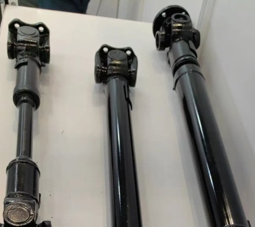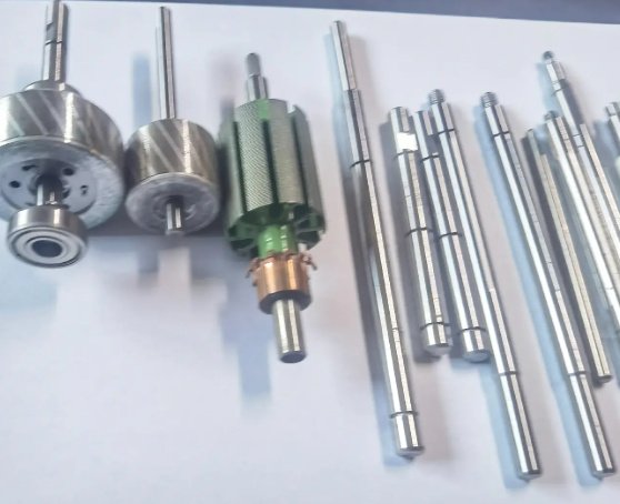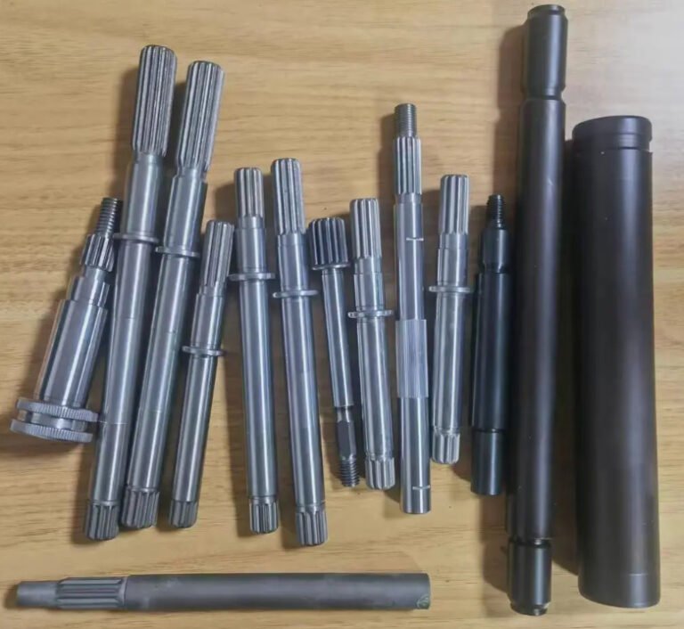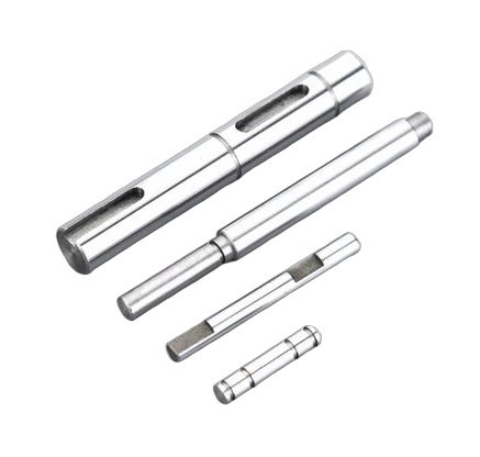
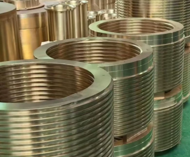
A shaft sleeve is a replaceable cylindrical component fitted over a rotating shaft to protect the shaft surface, provide a controlled wear interface, support sealing performance, or create a defined mounting surface for related rotating equipment. In pumps, mixers, compressors, conveyors and marine drives, shaft sleeves help reduce shaft replacement cost, improve maintenance speed and control wear in the area exposed to seals, bearings, packing, corrosive fluids or abrasive solids.
For engineers and buyers, the main search intent is usually practical: which sleeve type is correct, what material should be specified, what tolerance is required, and how the sleeve compares with bushings, couplings or direct shaft hardening. This guide explains the difference between a shaft sleeve bushing, a protective sleeve, a wear sleeve and a shaft sleeve coupling, with machining and procurement considerations included.
What Is a Shaft Sleeve?
A shaft sleeve is a hollow precision part mounted around a shaft. It can be shrink-fitted, press-fitted, keyed, threaded, clamped, bonded or mechanically locked depending on torque, speed, temperature and service environment. The sleeve may rotate with the shaft or, in some bearing and bushing arrangements, provide a replaceable sliding contact surface.
The basic concept of shaft and sleeve design is simple: protect the expensive or difficult-to-replace shaft by placing a smaller, replaceable component at the high-wear location. In rotating equipment, this can reduce maintenance cost significantly because replacing a sleeve is usually faster than manufacturing or replacing an entire shaft.
Common Functions of Shaft Sleeves
- Shaft protection: prevents scoring, corrosion, fretting and seal-groove wear on the original shaft.
- Seal running surface: provides a smooth, controlled surface for mechanical seals, packing or lip seals.
- Dimensional restoration: repairs worn shaft areas without replacing the complete shaft.
- Material upgrading: adds corrosion-resistant or hardened material only where needed.
- Assembly positioning: helps locate bearings, impellers, spacers or coupling components.
- Wear management: acts as a sacrificial part in abrasive, slurry, chemical or marine environments.
Types of Shaft Sleeves and Where They Are Used
Different shaft sleeves are designed for different mechanical purposes. The correct type depends on load, speed, chemical exposure, sealing method and installation constraints.
| Type | Typical Use | Key Design Concern |
|---|---|---|
| Protective shaft sleeve | Pumps, mixers, agitators, marine shafts | Corrosion resistance, seal surface finish, runout |
| Wear sleeve | Seal repair, worn shaft restoration | Thin-wall consistency, hardness, installation damage prevention |
| Spacer sleeve | Bearings, gearboxes, rotating assemblies | Face parallelism, axial length tolerance, squareness |
| Adapter sleeve | Bearing mounting on tapered seats | Taper accuracy, thread quality, locking method |
| Insulating sleeve | Electric motors, generators | Electrical isolation, temperature resistance |
| Coupling sleeve | Power transmission and shaft joining | Torque transfer, concentricity, keyway or spline accuracy |
Shaft Sleeve vs Bushing vs Coupling: Key Differences
Although the terms are sometimes used interchangeably in purchasing documents, they do not always describe the same function. Misidentifying the component can lead to incorrect material, wrong tolerance, premature wear or assembly failure.
| Component | Main Purpose | Rotates With Shaft? | Common Materials | Selection Priority |
|---|---|---|---|---|
| Shaft sleeve | Protects shaft or provides seal/wear surface | Usually yes | Stainless steel, bronze, alloy steel, coated steel | Wear, corrosion, concentricity, fit |
| Shaft sleeve bushing | Provides replaceable sliding or support interface | Depends on design | Bronze, graphite bronze, PTFE composite, polymer, stainless steel | Friction, lubrication, load, PV value |
| Shaft coupling | Connects two shafts for torque transmission | Yes | Steel, cast iron, aluminum, stainless steel | Torque, misalignment, balance, stiffness |
| Shaft sleeve coupling | Sleeve-like coupling used to connect or reinforce shaft ends | Yes | Alloy steel, stainless steel, hardened steel | Bore fit, keyway, torque capacity, locking method |
A shaft sleeve coupling is not simply a protective sleeve. It is generally designed to transmit torque between shaft sections or connect a shaft to another rotating part. Because it carries load, its bore tolerance, keyway accuracy, material strength and balance grade are more critical than those of a simple protective sleeve.
Material Selection for Shaft Sleeves
Material selection should be based on the fluid, temperature, shaft speed, mating seal material, required hardness and expected maintenance interval. A low-cost sleeve material may fail quickly if it cannot resist chloride corrosion, abrasive solids or fretting at the shaft interface.
| Material | Advantages | Limitations | Typical Applications |
|---|---|---|---|
| 304 stainless steel | Good general corrosion resistance, easy machining | Limited resistance to chlorides and severe abrasion | Water pumps, light-duty process equipment |
| 316 stainless steel | Improved chloride resistance over 304 | Not ideal for high-abrasion slurry without hardening or coating | Chemical pumps, marine water systems |
| Duplex stainless steel | Higher strength, better pitting resistance | Requires controlled machining and welding procedures | Offshore, desalination, corrosive process fluids |
| Bronze | Good anti-galling behavior, machinability | Lower hardness than hardened steels | Bushings, marine sleeves, low-friction interfaces |
| Hardened alloy steel | High wear resistance, strength | Needs corrosion protection in wet or chemical service | Heavy machinery, couplings, bearing spacer sleeves |
| Ceramic or carbide-coated sleeve | Excellent abrasion resistance and hard seal surface | Higher cost, coating integrity must be controlled | Slurry pumps, mining, paper pulp, wastewater |
In seal applications, the sleeve surface should be compatible with the seal face or packing material. For mechanical seals, surface finish often falls in the approximate range of Ra 0.2 to 0.8 micrometers depending on seal design, speed and fluid. For packing, a slightly different surface texture may be specified to retain lubrication without rapidly wearing the packing rings.
Machining Requirements and Tolerance Control
The machining route for a shaft sleeve normally includes material cutting, rough turning, heat treatment if required, finish turning, boring, grinding or honing, keyway cutting, threading, slotting, coating and final inspection. For high-speed rotating equipment, concentricity and dynamic balance can be as important as material selection.
Important Machining Features
- Inner diameter tolerance: determines press fit, slip fit or shrink fit behavior on the shaft.
- Outer diameter tolerance: controls seal contact, bearing support or coupling alignment.
- Total indicated runout: helps prevent seal leakage, vibration and uneven wear.
- Surface finish: affects seal life, friction, heat generation and packing wear.
- Face squareness: important when the sleeve locates impellers, bearings or spacers axially.
- Keyway accuracy: critical for torque transfer in driven sleeves and coupling sleeves.
- Chamfers and lead-ins: reduce seal damage and improve assembly reliability.
Typical engineering references include ISO 286 for limits and fits, ISO 21940 for rotor balancing, ISO 1940 legacy balance guidance, API 610 for centrifugal pumps in petroleum and process industries, and ASME B73.1 for horizontal end-suction chemical pumps. Actual tolerances must still be defined by the equipment drawing and service duty.
Engineer and buyer notes for specifying a shaft sleeve
When sending an inquiry, include shaft diameter, sleeve length, wall thickness, material grade, hardness requirement, operating temperature, fluid or media, shaft speed, fit type, surface finish, runout requirement and whether the sleeve contacts a mechanical seal, packing, bearing, bushing or coupling. If the sleeve replaces an OEM part, provide the part number and worn sample dimensions, but do not rely only on worn dimensions for new production.
Fit Methods: Press Fit, Shrink Fit, Slip Fit and Locking Designs
The fit between the shaft and sleeve determines whether the sleeve can transmit torque, resist axial movement and avoid fretting corrosion. A loose sleeve can cause vibration, scoring and leakage. An overly tight sleeve can crack, distort or make future maintenance difficult.
| Fit Method | Advantages | Risks | Best Use |
|---|---|---|---|
| Slip fit | Easy installation and replacement | May require set screws, nuts or shoulders to prevent movement | Pump sleeves, maintenance-friendly assemblies |
| Press fit | Good retention and concentricity when controlled | Can cause sleeve expansion, shaft scoring or assembly stress | Permanent or semi-permanent sleeve installation |
| Shrink fit | High holding force, uniform contact | Requires temperature control and accurate interference calculation | High-speed or high-load rotating parts |
| Keyed fit | Positive torque transmission | Keyway stress concentration and fretting if clearance is poor | Coupling sleeves, driven rotating components |
| Threaded sleeve | Axial retention and simple mechanical locking | Thread galling, loosening under vibration | Pump impeller sleeves and retained assemblies |
Real Engineering Problem: Pump Shaft Sleeve Wear
A common maintenance issue occurs in centrifugal pumps handling mildly abrasive process water. Packing or mechanical seals gradually cut grooves into the sleeve surface. Once the groove depth becomes significant, leakage increases, packing adjustment becomes frequent, and shaft vibration may rise due to uneven contact.
In one representative plant maintenance case, a standard stainless sleeve in an abrasive water pump required replacement about every 4 to 6 months. The sleeve surface showed circumferential grooves near the packing contact zone. After changing to a hardened, coated sleeve with improved runout control and a finish matched to the packing supplier’s recommendation, the maintenance interval increased to approximately 14 months. Leakage inspections were reduced from weekly adjustments to monthly checks under the same duty cycle. Results vary by media, packing type and alignment, but the case shows why sleeve material and finish should be treated as engineered variables rather than commodity details.
How to Choose the Right Shaft Sleeve
The best sleeve is not always the hardest or most expensive option. The right choice balances wear resistance, corrosion resistance, machinability, fit stability, seal compatibility and replacement cost. Buyers should evaluate total cost of ownership rather than unit price only.
Selection Checklist
- Confirm whether the part is a protective sleeve, bushing, spacer, adapter or coupling sleeve.
- Identify torque transmission requirements and whether a keyway, spline, thread or clamp is needed.
- Specify shaft diameter, fit class and installation method.
- Match material to media: water, seawater, chemicals, slurry, oil, steam or dry running.
- Define hardness, coating, heat treatment and corrosion resistance requirements.
- Set surface finish and runout requirements for seal-contact zones.
- Check whether dynamic balancing is required for high-speed rotation.
- Review maintenance access and whether field replacement must be possible.
Procurement comparison: OEM sleeve vs custom machined sleeve
An OEM sleeve is usually the safest option for warranty-controlled equipment and exact replacement. A custom machined sleeve can be preferable when lead time is long, the original design wears too quickly, the shaft has been repaired, or a material upgrade is required. For custom production, request an inspection report covering dimensions, material certificate, hardness if applicable, surface finish and concentricity.
Quality Inspection and Failure Prevention
Quality control should verify both dimensions and functional surfaces. A shaft sleeve may look simple, but small errors can produce leakage, overheating, fretting or premature bearing and seal failure.
Recommended Inspection Items
- Material verification: chemical composition certificate or PMI testing for stainless and alloy grades.
- Dimensional inspection: ID, OD, length, wall thickness, groove position and thread dimensions.
- Geometric control: roundness, cylindricity, concentricity, face runout and perpendicularity.
- Surface finish measurement: especially in seal, packing and bearing contact zones.
- Hardness testing: required for hardened, coated or wear-resistant sleeves.
- Coating inspection: thickness, adhesion and cracks for carbide, ceramic or sprayed coatings.
- Balance check: required for high-speed or large-diameter rotating sleeves.
Common causes of premature sleeve failure
Premature failure is often caused by shaft misalignment, excessive sleeve runout, wrong surface finish, chemical attack, galvanic corrosion, dry running, poor packing adjustment, incorrect interference fit, keyway fretting, abrasive contamination or installation damage. Before replacing a failed sleeve with the same design, inspect the seal system, bearing condition, shaft straightness and operating environment.
Conclusion
A shaft sleeve is a precision wear and protection component, not just a simple tube. Correct selection requires understanding the application, material environment, fit method, machining tolerance and inspection requirements. Whether the requirement is a pump sleeve, shaft sleeve bushing, repair wear sleeve or shaft sleeve coupling, the most reliable result comes from matching sleeve design to the actual mechanical duty and maintenance strategy.