
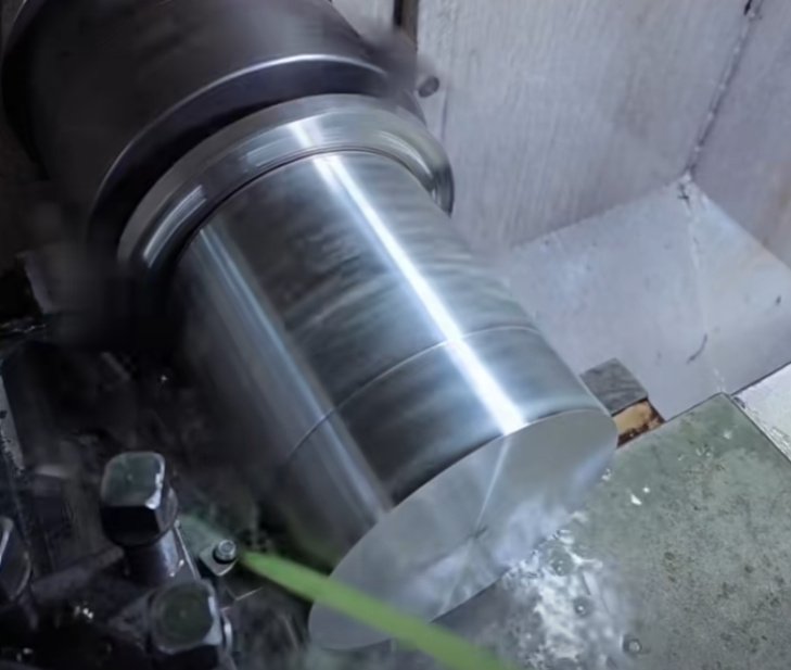
Achieving tight tolerances and superior surface finish on Hastelloy components is a critical challenge for industries like aerospace, semiconductor tooling, and precision medical devices, where dimensional accuracy directly dictates functional performance and longevity. Unlike conventional metals, Hastelloy's high strength, rapid work hardening, and low thermal conductivity make standard high-speed machining strategies ineffective, often resulting in scrap parts, thermal distortion, and poor surface integrity that compromises corrosion resistance. This guide details the specialized CNC techniques, toolpath strategies, and process controls essential for consistently holding tolerances within ±0.005 mm (0.0002") and achieving surface roughness (Ra) below 0.4 μm on complex Hastelloy parts.
1. The Core Challenge: Material Behavior vs. Precision Requirements
Hastelloy's properties that provide excellent service performance—namely, its high hot hardness and tendency to work harden—are the same properties that make precision machining exceptionally difficult. When attempting to hold tight tolerances, the primary obstacles are thermal growth during cutting and elastic springback after machining. The low thermal conductivity of Hastelloy C-276 (approximately 11.2 W/m·K) means heat concentrates in the cutting zone and the part itself, not in the chips. This localized heating can cause the workpiece to expand measurably during machining, leading to a part that measures correctly on the machine but shrinks out of tolerance after cooling.
Furthermore, the material's high yield strength and elasticity mean it will spring back after the cutting tool passes, especially during thin-wall machining. If not accounted for, this results in a tapered bore or a wall thicker than programmed. Data from precision aerospace component manufacturers shows that uncorrected thermal and elastic effects can cause final dimensions to deviate by up to 0.02 mm on a 100 mm feature, far exceeding the typical ±0.005 mm tolerance required for fuel system or valve components.
Key material properties affecting precision machining of Hastelloy
- Work Hardening Rate: Can increase surface hardness by 100-150 HV after a single improper cut.
- Thermal Expansion Coefficient: ~11.5 μm/m·°C. A 10°C temperature rise in a 200mm part causes 0.023mm growth.
- Modulus of Elasticity: ~205 GPa, leading to significant tool pressure and springback.
- Affinity for Tool Materials: High tendency to weld to cutting tool edges, causing built-up edge (BUE) and poor finish.
2. Machine Tool and Workholding: The Foundation of Precision
Attempting high-precision Hastelloy machining on a standard CNC mill or lathe is a primary cause of failure. The foundation requires a machine tool system designed for stability and thermal control. A high-rigidity, thermally symmetric machine tool with a cooled spindle and ball screws is non-negotiable. Look for machines with a static stiffness rating above 50 N/μm and spindle thermal growth compensation. Vibration, even at low amplitudes, will manifest as chatter marks on the finished surface, destroying Ra values and accelerating tool wear.
Workholding must provide uniform, high clamping force without distorting the part. For thin-walled Hastelloy components, hydraulic or pneumatic expanding mandrels and custom soft jaws machined in-situ are preferred. Vacuum chucks are excellent for plate work, as they distribute holding force evenly and minimize part distortion. A critical best practice is to perform a "proof cut" on a dummy piece to measure actual clamping deformation before machining the final part.
3. Tooling and Parameter Strategy for Micron-Level Accuracy
Tool selection moves beyond general-grade carbide. For finishing operations aiming for Ra < 0.4 μm, micro-grain or sub-micron grain carbide with a specialized PVD coating like AlTiN/SiN is required. The tool geometry must be sharp with a large positive rake angle (12°-15°) and a honed cutting edge to shear the material cleanly, minimizing plowing and work hardening. For the final finishing pass, a wiper insert geometry can effectively smooth the surface by trailing over the freshly cut peaks.
The parameter philosophy for tight tolerances is "low speed, high feed, constant engagement." Contrary to intuition, reducing cutting speed (Vc) to 25-35 m/min for finishing minimizes heat generation. Increasing feed per tooth (fz) to 0.1-0.15 mm ensures the tool is cutting, not rubbing. Most importantly, use trochoidal or peel milling toolpaths for pockets and slots to maintain constant radial engagement (often 5-10% of tool diameter), which provides consistent cutting forces, reduces vibration, and manages heat. Implementing this strategy has been shown to improve dimensional consistency by over 60% and achieve surface roughness values consistently between Ra 0.3-0.4 μm.
4. In-Process Control: Compensation for Thermal and Elastic Effects
Advanced in-process techniques are required to hit sub-0.01 mm tolerances. First, implement a high-pressure through-spindle coolant (TSC) system at a minimum of 70 bar to evacuate heat directly from the cut. Second, use a "rough, stabilize, finish" sequence: after roughing, remove the part from the fixture, perform a stress-relief (stabilization) heat treatment, then re-fixture for semi-finishing and final finishing. This breaks the internal stress cycle that causes distortion.
For critical features, use on-machine probing to measure the part after a semi-finish cut while it's still at operating temperature. The CNC program can then automatically compensate the tool path for the measured thermal expansion or springback. For example, if a bored hole measures 0.008 mm undersize at 35°C part temperature, the program can adjust the final bore cut to account for the predicted 0.005 mm contraction upon cooling to 20°C.
5. Post-Machining Validation and Surface Integrity
Final inspection must go beyond CMM dimensional checks. The surface integrity of a precision Hastelloy part is as critical as its dimensions. A polished surface with embedded micro-cracks or a work-hardened layer will fail prematurely in corrosive service. Use white light interferometry or a portable surface profilometer to verify Ra, Rz, and waviness (Wa) parameters.
Conduct a micro-hardness traverse test from the surface into the base material to ensure the work-hardened layer is less than 0.05 mm deep. For parts in cyclic load service, fluorescent penetrant inspection (FPI) is recommended to detect any micro-cracks induced by aggressive machining. Finally, a passivation or electropolishing step may be specified not only to enhance corrosion resistance but also to lightly etch the surface, revealing any hidden machining defects.
Conclusion
Precision machining of Hastelloy to tight tolerances and fine finishes is a systematic discipline that integrates machine tool capability, specialized tooling, adaptive toolpaths, and in-process compensation. It requires moving away from standard machining paradigms and adopting a controlled, low-heat, high-stability approach. By mastering these techniques, manufacturers can reliably produce Hastelloy components that meet the exacting standards of advanced industries, ensuring both dimensional perfection and the preservation of the alloy's legendary in-service performance.