A carbon steel shaft is a cylindrical mechanical component used to transmit torque, support rotating parts, locate bearings, and maintain alignment in machinery. For many conveyors, gearboxes, pumps, agricultural machines, packaging systems, and general industrial assemblies, Carbon Steel Shafts offer an effective balance of strength, machinability, wear resistance, and cost.
This page explains common shaft materials, machining choices, heat treatment methods, dimensional requirements, comparison points, and engineering considerations so that buyers, engineers, and sourcing teams can specify a shaft that matches the actual load, speed, bearing arrangement, and service environment.
What Is a Carbon Steel Shaft?
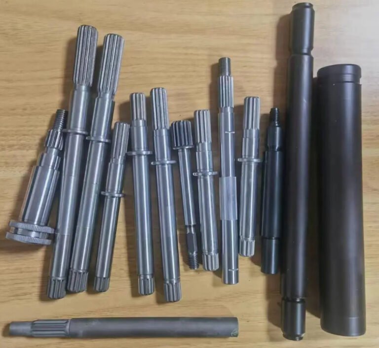
A carbon steel shaft is typically produced from carbon steel round bar, forged bar, cold-drawn bar, or turned-ground-polished stock. It may be supplied as a plain shaft, stepped shaft, keyed shaft, splined shaft, threaded shaft, drilled shaft, or fully machined shaft ready for assembly.
Compared with stainless steel or high-alloy steel shafts, carbon steel shafts are commonly selected when the operating environment is not highly corrosive and when the design requires good mechanical strength at a competitive unit cost.
- Typical material families: AISI 1018, 1020, 1045, 1050, C45, EN8, S45C, CK45
- Common production forms: hot-rolled bar, cold-drawn bar, TG&P shafting, forged shaft blank
- Common features: keyways, flats, grooves, shoulders, threads, circlip grooves, bearing journals, cross holes
- Common finishing options: black oxide, phosphate coating, zinc plating, oil coating, induction hardening, hard chrome plating
Common Types of Carbon Steel Shafts
Carbon steel shaft designs vary according to torque transmission, bearing support, coupling method, and assembly layout. The most suitable type depends on the required geometry and manufacturing tolerance.
| Type | Description | Typical Use |
|---|---|---|
| Plain round shaft | Straight cylindrical shaft with uniform diameter | Rollers, guides, light-duty transmission, support rods |
| Stepped shaft | Multiple diameters with shoulders for locating components | Gearboxes, motor shafts, pump shafts, reducers |
| Keyed shaft | Machined keyway for torque transfer through a key and hub | Sprockets, pulleys, gears, couplings |
| Splined shaft | External or internal splines for high torque and axial sliding | Drivetrain parts, clutches, hydraulic equipment |
| Threaded shaft | External or internal threads for fastening or adjustment | Actuators, tensioning systems, custom machinery |
| Induction hardened shaft | Hardened surface with tougher core | Linear motion, wear surfaces, bearing contact zones |
Material Grades for Carbon Steel Shafts
Material grade selection should be based on strength, machinability, heat treatment response, surface hardness requirement, and availability. For most industrial shafting, medium carbon steel is preferred when higher torque capacity or wear performance is required.
| Grade | Equivalent or Similar Grade | Typical Carbon Content | Engineering Characteristics |
|---|---|---|---|
| AISI 1018 | EN C15, low carbon steel | About 0.18% | Excellent machinability and weldability; suitable for light-duty shafts and carburized parts |
| AISI 1020 | C22, mild steel | About 0.20% | Good weldability and economical for general structural shaft applications |
| AISI 1045 | C45, CK45, S45C | About 0.45% | Widely used for medium-duty and heavy-duty shafts; good strength and heat treatment response |
| EN8 | 080M40, similar to 1040/1045 | About 0.40% | Common engineering steel for shafts, studs, pins, and rotating components |
| 1050 | C50, S50C | About 0.50% | Higher hardenability than mild steel; useful where surface hardness and strength are important |
For many machined Carbon Steel Shafts, AISI 1045 or C45 is a practical default because it provides a strong combination of tensile strength, wear resistance, machinability, and global material availability.
Carbon Steel Shaft vs Stainless Steel, Alloy Steel and Aluminum Shaft
Material comparison is essential because shaft failure is often caused by using a material that is strong in one category but unsuitable for the actual environment or load case. The table below summarizes common selection trade-offs.
| Material | Main Advantage | Limitation | Best Fit |
|---|---|---|---|
| Carbon steel shaft | Cost-effective strength, good machinability, broad availability | Requires coating or oil protection in corrosive environments | General machinery, conveyors, rotating equipment, industrial drives |
| Stainless steel shaft | Corrosion resistance and clean appearance | Higher cost; some grades have lower machinability or galling risk | Food processing, marine exposure, chemical equipment, washdown areas |
| Alloy steel shaft | Higher hardenability, fatigue strength, and toughness | Higher material and heat treatment cost | High-load gear shafts, mining machinery, automotive drivetrain parts |
| Aluminum shaft | Low weight and good corrosion resistance | Lower modulus and lower wear resistance than steel | Light-duty equipment, weight-sensitive assemblies, non-heavy torque parts |
A practical rule is simple: choose carbon steel when the priority is economical mechanical strength, choose stainless steel when corrosion resistance dominates, choose alloy steel when fatigue and impact loads are severe, and choose aluminum when weight reduction is more important than stiffness and wear life.
Engineering comparison note: carbon steel and stainless steel stiffness
Many buyers choose stainless steel expecting it to be mechanically “stronger,” but stiffness is mainly controlled by the modulus of elasticity. Carbon steel and most stainless steels have similar elastic modulus values, generally around 190 to 210 GPa. In many dry indoor applications, a carbon steel shaft can deliver comparable deflection performance at lower cost, provided corrosion protection is adequate.
Manufacturing and Machining Options
The performance of a carbon steel shaft depends not only on material grade but also on how it is produced, machined, heat treated, and inspected. Shaft manufacturing usually begins with round bar cutting, followed by turning, milling, drilling, grinding, heat treatment, straightening, finishing, and final inspection.
Turning and CNC Machining
CNC turning is used to create outside diameters, shoulders, grooves, chamfers, threads, and bearing seats. For complex shafts, live-tool turning centers can also machine keyways, cross holes, flats, and radial features in one setup, improving concentricity and reducing handling error.
Keyway, Spline and Flat Milling
Keyways are common on power transmission shafts because they allow torque transfer from the shaft to gears, sprockets, pulleys, and couplings. Splines are preferred when torque is higher or when axial movement is required. Flats may be used for set screws, clamping hubs, or position reference surfaces.
Grinding and TG&P Shafting
Turned, ground and polished shafting, often called TG&P shafting, is selected when bearing journals or sliding contact areas require tighter diameter tolerance, improved roundness, and smoother surface finish. Ground carbon steel shafting is commonly used with bearings, bushings, seals, and linear motion components.
Heat Treatment and Surface Hardening
Medium carbon steels such as 1045, C45 and EN8 respond well to heat treatment. Induction hardening can produce a hard wear-resistant surface while retaining a tougher core, which is valuable for shafts exposed to rolling contact, sliding wear, or repeated assembly movement.
- Normalized 1045 steel may reach approximately 570 to 700 MPa tensile strength depending on specification and section size.
- Induction hardened 1045 shaft surfaces commonly reach about HRC 50 to 55 when properly processed.
- Ground bearing journals often require surface roughness around Ra 0.8 micrometers or better, depending on bearing and seal requirements.
- General machined shaft diameters may use ISO h9, h8, h7, or custom tolerances according to fit requirements.
Machining note: why shaft shoulders need radius control
Sharp internal corners create stress concentration and can initiate fatigue cracks. When a shaft has steps for bearings or gears, the shoulder fillet radius should be large enough to reduce stress concentration but small enough to clear the mating component chamfer. This small design detail can significantly improve rotating shaft life.
Engineering Performance Factors
Shaft design should consider torque, bending moment, combined stress, fatigue, impact load, operating speed, deflection, bearing spacing, keyway stress concentration, surface finish, and corrosion exposure. A low-cost shaft that meets only diameter requirements may still fail if fatigue strength, runout, or hardness is not properly specified.
Torque and Diameter
Shaft torque capacity increases rapidly with diameter because polar section modulus is related to the cube of diameter. In practical terms, a small diameter increase can produce a meaningful reduction in torsional shear stress. This is why engineers often review shaft diameter before moving to a more expensive material grade.
Deflection and Bearing Life
Excessive shaft deflection can reduce bearing life, cause seal leakage, increase vibration, and create gear misalignment. For rotating assemblies, the shaft should be checked not only for strength but also for stiffness and critical speed.
Runout, Straightness and Balance
Straightness and runout affect vibration, seal performance, bearing loading, and component alignment. Long carbon steel shafts may require straightening after heat treatment or rough machining. High-speed shafts may also need dynamic balancing after final machining and assembly of rotating components.
Surface Finish and Wear
Surface roughness affects bearing fit, seal wear, corrosion resistance, and fatigue strength. Ground and polished surfaces are preferred where there is contact with seals, bushings, needle bearings, or linear bearings. For plain power transmission shafts, turned finishes may be acceptable when tolerances and surface contact requirements are less demanding.
Example engineering result: reducing shaft wear in a conveyor drive
In a conveyor drive application using a 40 mm diameter keyed shaft, premature wear appeared near the bearing journal after repeated start-stop loading. The original shaft used untreated medium carbon steel with a turned journal. By changing to a 1045 carbon steel shaft with induction hardened bearing contact zones and ground journals, the surface hardness increased to approximately HRC 52 and journal roughness improved to about Ra 0.8 micrometers. The modification reduced fretting marks during maintenance inspection and improved bearing seat stability under cyclic load.
Recommended Specifications for Buyers and Engineers
A complete shaft inquiry or engineering drawing should define more than length and diameter. Clear specifications reduce quotation variation, prevent fit issues, and help suppliers choose the correct process route.
| Specification Item | Why It Matters | Typical Information to Provide |
|---|---|---|
| Material grade | Controls strength, machinability, hardness and heat treatment response | 1045, C45, EN8, 1018, S45C or required standard |
| Overall length and diameters | Defines geometry, blank size and shaft machining route | Nominal dimensions with tolerances |
| Critical fits | Prevents loose bearings, difficult assembly or excessive runout | h7, h8, press fit, slip fit, bearing manufacturer recommendation |
| Keyways and splines | Defines torque transfer features | Width, depth, length, standard, position tolerance |
| Heat treatment | Improves hardness, strength or wear resistance | Normalized, quenched and tempered, induction hardened, case depth |
| Surface finish | Affects sealing, wear, fatigue and corrosion protection | Ra value, grinding requirement, coating, plating, oil protection |
| Straightness and runout | Important for rotating speed, vibration and bearing life | Total indicator runout, datum reference, straightness tolerance |
| Inspection documents | Supports quality control and traceability | Material certificate, hardness report, dimensional report, surface finish report |
From a procurement perspective, the best-priced shaft is often not the cheapest raw bar; it is the part with the fewest rework risks, the correct tolerance level, reliable material traceability, and a manufacturing process matched to the final assembly conditions.
Quality Control and Inspection
Quality control for carbon steel shafting should verify both mechanical requirements and dimensional accuracy. For precision shafts, inspection may include material identification, hardness testing, diameter measurement, roundness, straightness, concentricity, runout, keyway position, thread gauge inspection, surface roughness testing, and visual inspection for cracks or machining defects.
- Material traceability: heat number, mill certificate and chemical composition report when required.
- Dimensional inspection: micrometers, height gauges, CMM, thread gauges and dedicated fixtures.
- Hardness verification: Rockwell, Brinell or Vickers testing according to heat treatment requirement.
- Surface quality: roughness measurement, coating thickness test, visual inspection and corrosion protection check.
- Rotational accuracy: straightness, concentricity and total indicator runout inspection for rotating assemblies.
If the shaft is used in a safety-critical or high-speed machine, non-destructive testing such as magnetic particle inspection may be specified to detect surface or near-surface discontinuities after heat treatment and machining.
Typical Applications of Carbon Steel Shafts
Carbon steel shafts are used across industries because they can be manufactured in small batches, large production runs, standard stock lengths, or fully customized machined configurations.
- Conveyor rollers, drive shafts and idler shafts
- Gearbox input shafts, output shafts and intermediate shafts
- Pump shafts, fan shafts and blower shafts
- Agricultural equipment shafts and power transmission components
- Packaging machine shafts, guide shafts and cam shafts
- Construction machinery pins, axles and rotating support shafts
- Automotive and industrial fixture shafts
- Linear motion guide shafts when hardened and ground surfaces are required
How to Select the Right Carbon Steel Shaft
The right carbon steel shaft should be selected by matching grade, geometry, tolerance, surface hardness, and finishing method to the operating conditions. For light-duty welded assemblies, low carbon steel such as 1018 or 1020 may be sufficient. For general power transmission, 1045, C45 or EN8 is often more suitable. For wear surfaces, induction hardening and grinding may be more important than simply increasing material grade.
In many industrial applications, carbon steel shafting provides the most practical balance between performance and cost. The key is to specify the part as a functional machine element rather than a generic round bar: define the loads, fits, runout, heat treatment, surface finish, coating, and inspection requirements before production begins.